


A study on VLM-driven ceiling fan airflow analysis w/ Unity
September 29, 2026




Navigation Bar
Apply Theme
- Introduction
- Keywords
- Brands
- Hardware
- Software
- Description
- Development process, device overview, and final results
- Step 1: Building the electrical structure of the ceiling fan mechanism
- Step 1.1: Building the ceiling fan mechanism control circuit based on Nano 33 BLE
- Step 2: Programming the Arduino sketch executed by the Nano 33 BLE
- Step 3: Designing the ceiling fan mechanical controller PCB (4-layer) based on Nano 33 BLE
- Step 3.1: Soldering and assembling the ceiling fan mechanical controller PCB
- Step 4: Modeling the ceiling fan mechanism mechanical components
- Step 4.a: Designing the ceiling fan controller PCB case
- Step 4.a.1: Printing and assembling the ceiling fan controller PCB case
- Step 4.b: Designing the differential bevel gear mechanism with 2 DoF
- Step 4.b.1: Printing and assembling the differential bevel gear mechanism
- Step 4.c: Designing and assembling the RPLIDAR A1M8 elevation mount
- Step 5: Developing a BLE-enabled and web-enabled mobile application in MIT App Inventor 2
- Step 6: Setting up required LLM/VLM packages and software on the Dragonwing IQ-9075 EVK
- Step 6.1: Setting up an environment for the Flask web application on the Dragonwing IQ-9075 EVK
- Step 7: Developing the intermediary Flask web application
- Step 8: Developing the ceiling fan LiDAR-based airflow simulation application in the Unity Editor
- Step 8.1: Building the Unity airflow simulation application and running it on the Dragonwing IQ-9075 EVK
- Step 9: Combining all IQ-9075 EVK operations to run with a single Bash script
- Step 10: Completing the assembly of the ceiling fan system in conformity with its digital twin
- Outcome: Conducting VLM-assisted airflow analysis on the Unity-produced airflow simulation frames to determine optimal ceiling fan configurations for efficient cooling
- Outcome: Testing LiDAR-based airflow simulation and VLM-assisted airflow analysis in different scenarios
- Project GitHub Repository
- Schematics
- Code
- Custom assets
- See on other platforms
- Related projects
Utilizing VLMs to determine dual fan configurations for optimum cooling based on LiDAR-oriented real-time airflow simulations on Unity.
Keywords
Hardware
- 1Dragonwing IQ-9075 EVK
- 1RPLIDAR A1M8-R6 LiDAR Scanner
- 1Custom PCB (4-layer)
- 1Arduino Nano 33 BLE
- 2BTS7960B DC Motor Driver Module
- 2RS775 12V DC Motor (12000 rpm)
- 4A4988 Stepper Motor Driver Module
- 4Nema 17 (17HS3401) Stepper Motor
- 2KY-040 Rotary Encoder Module
- 2LM393 Optical Motor Speed Module
- 4100 nF Ceramic Disc Capacitor
- 1Grove - Triple Color E-Ink Display (1.54")
- 12 Channel Relay Module
- 1ELECROW CrowVision 11.6'' TouchScreen Module (1366x768)
- 1UGREEN 5-in-1 100W USB-C Hub
- 112V 29A Enclosed Switching Power Supply (MT-350-12)
- 14 Pole Power Distribution Block (4x7 125A)
- 1Copper Cable (2 x 1.5 mm²)
- 1Copper Cable (2 x 0.75 mm²)
- 1Insulated Ring Crimp Terminals
- 1Male Plug (grounded)
- 1Female Plug (grounded)
- 22700K Amber Vintage LED Filament Bulb
- 2Black E27 Threaded Lamp Holder
- 3KF2EDGR-5.08-2P Vertical Screw Terminal
- 1M2 Screws, Nuts, and Washers
- 1M3 Screws
- 1Jumper Wires
- 1Bambu Lab A1 Combo
- 1IKEA LACK Table (Black 55x55 cm)
Software
Description
As consecutive heatwaves were passing through my region at the beginning of Summer, I had been intrigued to develop a research project regarding AI-oriented HVAC simulations to increase real-world cooling efficiency both energy-wise and coverage-wise. Although there were meticulous research papers, even commercial firms providing services to analyze the cooling efficiency of air conditioning units by thorough HVAC simulations, I decided to focus on developing my project around ceiling fans. Even though ceiling fans are not as popular as air conditioning units nowadays, I had noticed there were a plethora of ceiling fan installations in my city, especially in historic shopping districts, bazaars, and government establishments. Thus, I decided to focus my research on simulating ceiling fan-induced airflow and deriving optimal system settings from this simulation for efficient cooling.
Considering I wanted to see the impact of AI-oriented simulations on deriving optimum configurations for a real-world ceiling fan system, I decided to design a dual ceiling fan mechanism from scratch, enabling me to control all experiment parameters while building my ceiling fan airflow simulation program. Though a little untraditional, I decided to base my dual ceiling fan design on a differential bevel gear mechanism to be able to move both fans 180° vertically and 360° horizontally, leading to a lot more complicated but comprehensive simulation-driven airflow analysis and real-world cooling efficiency improvements.
After deciding on the bare bones of the dual ceiling fan mechanism, I needed a method to map the surroundings of operating ceiling fans since a precise airflow simulation must include real-time obstacle updates to analyze airflow path fluctuations triggered by solid surfaces such as walls, open doors, windows, or even moving people. Generally, HVAC simulations for industrial settings utilize highly sensitive 3D LiDARs with SLAM or sensor fusion techniques to generate accurate heat maps. Nonetheless, since I wanted to focus on fan-produced indoor airflow analysis for much simpler settings, I decided to utilize an RPLIDAR A1M8-R6 LiDAR scanner and turn its 2D scan points into a simple 3D obstacle map in my airflow simulation program, enabling fan-produced air displacement routes (trails) to bounce off of their surfaces.
In the spirit of making the ceiling airflow simulation program easily accessible and open-source, I decided to utilize Unity to develop all airflow analysis features, including the obstacle generation from 2D LiDAR scan points, without utilizing any third-party or paid Unity services. Although Unity might seem like an odd choice since it is a cross-platform, performance-focused 3D game engine, I wanted to capitalize on its advanced scene and animation rendering features in order to simulate accurate airflow fluctuations and track fan-produced air displacement routes (trails). In this regard, I was able to obtain animation-based frames individually for each pre-defined ceiling fan configuration (angles, fan strength, etc.), enabling me to conduct airflow analysis by taking instances from a long animation (video) sequence.
To derive optimal ceiling fan configurations from selected airflow simulation frames so as to achieve real-world efficient cooling, I decided to utilize vision–language models (VLMs) running locally. As I wanted to demonstrate the performance of open-source vision–language models without tailoring model output for a specific ceiling fan-installed space, I did not train any models beforehand. In this regard, I was able to see whether off-the-shelf open-weight vision–language models could be deployed to obtain airflow simulation-based ceiling fan configurations to achieve energy-efficient and optimal cooling of a real-world closed environment. I thoroughly discussed my findings in the following tutorial, but I can briefly state that the vision-language models (Qwen) I employed performed well and provided effective fan configurations based on the obstacle map derived from 2D LiDAR scan points.
- Qwen2.5-VL-7B-Instruct
- Qwen3-VL-8B-Instruct
As I wanted to calculate 2D LiDAR scan points, execute the Unity ceiling fan-produced airflow simulation application, and run vision-language models on the same device to achieve fast and reliable simulation-based airflow analysis results, I decided to utilize the Qualcomm Dragonwing IQ-9075 Evaluation Kit (EVK), which is a compact development platform optimized for industrial IoT, Edge AI, and robotics applications involving heavy workloads. Thanks to the IQ-9075's dedicated AI Engine (Hexagon NPU) for on-device AI, I was able to execute operations separately to achieve excellent calculation, simulation, and inference performance, which is still bemusing to me considering the compactness of the EVK :)
To provide a user-friendly interface to select Unity-generated airflow simulation frames and communicate with the provided vision-language models, I developed a simple web application running on Flask, behaving as the intermediary between the Unity airflow simulation application and the local LLM/VLM server — Qualcomm Docker Compose container.
- Octa-core Kryo CPU ➡️ LiDAR scan points and other calculations
- Adreno GPU (with CPU) ➡️ Unity airflow simulation application
- Hexagon NPU ➡️ Vision-language models (VLMs)
Even though I obtained great airflow analysis results from vision-language models, I did not want to create a direct pipeline between the VLM outputs and ceiling fan mechanism controls, considering potential hallucinations and false positives. Furthermore, I wanted to enable the user to access all of the ceiling fan mechanism controls without impediments by not concealing fan configurations behind VLM outputs, including the dual light bulbs I added, since the ceiling fan with an on-device light source is a widely preferred household good. Since I did not want to create a secondary web-based interface for the fan configurations, I decided to develop a BLE-enabled mobile (Android) application, embedding the previously mentioned intermediary (Flask) web application. In this regard, all of the ceiling fan mechanism controls and VLM interactions can be inspected and adjusted on a single mobile application. The mobile application allows the user to:
- ✅ adjust ceiling fan vertical (180°) and horizontal (360°) angles for both fans,
- ✅ adjust ceiling fan strength magnitudes from 1 to 4,
- ✅ control light source states (on or off),
- ✅ observe current vertical angles and horizontal axis alignment states,
- ✅ connect to the intermediary web application to interact with the provided VLMs.
To enable the mobile application to manage ceiling fan mechanism configurations over BLE without putting any additional stress on the compute power of the IQ-9075 EVK, I decided to utilize a separate board, Arduino Nano 33 BLE, to control all mechanical features. I designed a unique 4-layer PCB to build a compact fan control unit based on the Nano 33 BLE, which provides all the required connections for the external power source, stepper motor drivers, DC motor drivers, lights, rotary encoders, optical speed modules, etc., to execute all of the ceiling fan mechanism features noted above.
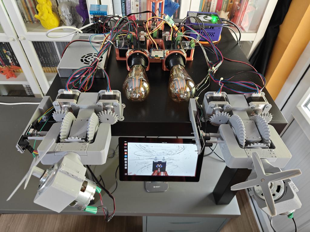
As a proof-of-concept research project, I did not focus on building a directly installable ceiling fan system ready to cool an enclosed space like a commercially available product. Instead, I focused on developing a VLM-assisted ceiling fan mechanism that showcases intricate circuit connections, wiring, device structure, and a simulation-based airflow analysis pipeline. Thus, I immensely scaled down the intertwined VLM-assisted ceiling fan mechanism I envisioned and highlighted the fan elevation by placing the whole mechanism on an IKEA LACK table, which enabled me to create a highly detailed digital twin of the ceiling fan system in Fusion 360 and integrate this exquisite 3D model into the Unity Editor to develop an utterly accurate Unity airflow simulation application, estimating airflow fluctuations and air displacement routes (trails) based on the fan elevation and the LiDAR-detected obstacles.
🎁🎨 Some of the components I reutilized in this project were kindly sponsored for my previous projects:
⭐ Huge thanks to DFRobot for sending me an RPLIDAR A1M8-R6 LiDAR scanner.
⭐ Huge thanks to ELECROW for sending me a CrowVision 11.6'' touchscreen module.


Development process, device overview, and final results
As mentioned, I needed to develop Unity, web, and mobile applications working in collaboration to achieve the VLM-assisted ceiling fan features and LiDAR-based airflow simulation. In addition to developing these applications, designing the ceiling fan mechanical components, electrical circuit, and the unique 4-layer PCB was quite a challenge, considering the custom differential bevel gear mechanism controlling the vertical and horizontal positions of the ceiling fans. Although I documented my thought process and development steps in the following written tutorial, I highly recommend checking the project demonstration video with timestamps for a brief overview, as showing is always more preferable than telling for a research project :)
Step 1: Building the electrical structure of the ceiling fan mechanism
Even though this is a greatly scaled-down version of a ceiling fan system, I wanted to build a high-grade primary electrical structure to supply RS775 DC motors, Nema 17 stepper motors, dual light bulbs, the IQ-9075 EVK, the Nano 33 BLE, and all of the remaining electrical components, such as the rotary encoders.
Thus, I utilized professional routing products to obtain power from the main electric line (grid), as if the fan mechanism were installed on the ceiling, and distribute power to each electrical component respectively.
#️⃣ First, I soldered jumper wires to the RS775 DC motors (12V) via my TS100 soldering iron and sealed the connection ends with heat-shrink tubing. I utilized jumper wires only for testing and replaced them with 2 x 0.75 mm² copper cables for the final version, since jumper wires could not provide enough current to run the DC motors at their full potential.


#️⃣ Then, I built the primary supply circuit. I represented the grid connection via a male grounded plug carrying voltage through a 2 x 1.5 mm² copper cable.
#️⃣ I utilized a 4-pole power distribution block (4x7 125A) to separate the grid connection to power the electrical components mentioned below.
#️⃣ To power the IQ-9075 EVK, the Nano 33 BLE, and the touchscreen module, I used a female grounded plug connected to the distribution block via a 2 x 1.5 mm² copper cable, since these parts require tailored chargers.
#️⃣ I utilized 2 x 0.75 mm² copper cables (split) to power the E27 threaded lamp holders directly through the 2-channel relay module.
#️⃣ I also utilized a 2 x 0.75 mm² copper cable (sheathed) to power the high-grade 12V switching power supply.
#️⃣ For each copper cable end connected to the distribution block, I installed insulated ring (crimp) terminals to ensure safe and intact electrical connections.


#️⃣ Finally, I connected the associated copper cable to the mentioned external power supply, which is a high-end 12V enclosed switching power supply (MT-350-12) and supports up to 29A. I chose this power supply since I needed to power multiple RS775 DC motors and Nema 17 (17HS3401) stepper motors, which demand high current loads, especially when working concurrently.


Step 1.1: Building the ceiling fan mechanism control circuit based on Nano 33 BLE
After completing the primary electrical structure, I started to work on the ceiling fan mechanism control circuit, consisting of motor driver modules, rotary encoders, and the electrical components required to achieve all of the ceiling fan features, including but not limited to the vertical and horizontal angle adjustments.
// Connections
// Arduino Nano 33 BLE :
//                                BTS7960B DC Motor Driver (40A) [First]
// 5V      ------------------------ VCC
// GND     ------------------------ GND
// D2      ------------------------ R_PWM
// D3      ------------------------ L_PWM
// 3.3V    ------------------------ R_EN
// 3.3V    ------------------------ L_EN
//                                BTS7960B DC Motor Driver (40A) [Second]
// 5V      ------------------------ VCC
// GND     ------------------------ GND
// D4      ------------------------ R_PWM
// D5      ------------------------ L_PWM
// 3.3V    ------------------------ R_EN
// 3.3V    ------------------------ L_EN
//                                A4988 Driver Module [First]
// 3.3V    ------------------------ VDD
// GND     ------------------------ GND
// D6      ------------------------ DIR
// D7      ------------------------ STEP
//                                A4988 Driver Module [Second]
// 3.3V    ------------------------ VDD
// GND     ------------------------ GND
// D8      ------------------------ DIR
// D9      ------------------------ STEP
//                                A4988 Driver Module [Third]
// 3.3V    ------------------------ VDD
// GND     ------------------------ GND
// D10     ------------------------ DIR
// D11     ------------------------ STEP
//                                A4988 Driver Module [Fourth]
// 3.3V    ------------------------ VDD
// GND     ------------------------ GND
// D12     ------------------------ DIR
// D13     ------------------------ STEP
//                                Grove - Triple Color E-Ink Display (1.54")
// GND     ------------------------ GND
// 3.3V    ------------------------ VCC
// TX      ------------------------ RX
// RX      ------------------------ TX
//                                2 Channel Relay Module
// GND     ------------------------ GND
// A6      ------------------------ IN1
// A7      ------------------------ IN2
// 5V      ------------------------ VCC
//                                KY-040 Rotary Encoder Module [First]
// GND     ------------------------ GND
// 3.3V    ------------------------ +
// A1      ------------------------ DT
// A0      ------------------------ CLK
//                                KY-040 Rotary Encoder Module [Second]
// GND     ------------------------ GND
// 3.3V    ------------------------ +
// A3      ------------------------ DT
// A2      ------------------------ CLK
//                                Motor Speed Sensor (LM393 Optical) [First]
// GND     ------------------------ GND
// A4      ------------------------ OUT
// 3.3V    ------------------------ VCC
//                                Motor Speed Sensor (LM393 Optical) [Second]
// GND     ------------------------ GND
// A5      ------------------------ OUT
// 3.3V    ------------------------ VCC
#️⃣ I utilized two RS775 12V DC motors (12000 rpm) as ceiling fan motors, which are powerful and reliable.
#️⃣ As I wanted to adjust the vertical and horizontal angles of the ceiling fans by designing a unique differential bevel gear mechanism with 2 DoF (Degrees of Freedom), I utilized two Nema 17 (17HS3401) stepper motors for each ceiling fan.
#️⃣ To drive the RS775 DC motors, I used BTS7960B DC motor driver modules, which support motors up to 40A and are more than enough for my RS775 motors able to draw 10A to 25A+ under heavy load or stall conditions.
#️⃣ To drive the Nema 17 stepper motors, I utilized well-known A4988 stepper motor driver modules. As discussed in the following steps, I increased the driver current limits by utilizing the onboard potentiometer to draw more power, since the default limit was not sufficient for vertical movements.
#️⃣ After pondering about tracking the vertical and horizontal angles of ceiling fans, I decided to utilize KY-040 rotary encoder modules to calculate the vertical position (angle). While designing the ceiling fan mechanism's mechanical parts, I ensured that the rotary encoders would be stationary and their shafts would align with the pivot axis of the differential bevel gear mechanism. In this way, I was able to estimate the vertical positions (angles) of both ceiling fans by directly tracking the encoder shaft rotations.
#️⃣ Since the Nano 33 BLE does not provide a stable internal 3.3V voltage and I needed to employ interrupt handlers to estimate vertical angle changes, I noticed that the rotary encoders produced fluctuating angle values, even when the shaft was not swiveling. Thus, I added two 100 nF ceramic disc capacitors between the associated Nano BLE pins and the encoder's CLK and DT lines; one leg to the encoder pin and the Nano BLE pin, the other leg to GND.
#️⃣ Since I wanted to enable the ceiling fans to rotate 360° horizontally, I did not need to track their exact horizontal positions. Nonetheless, I needed a way to determine once the ceiling fans' vertical axis becomes perpendicular to their horizontal axis, which makes the fans dissipate air at the highest elevation. As I wanted to determine this horizontal alignment via a non-contact detection method in order to avoid limiting the fans' movement, I decided to utilize LM393 optical motor speed modules. Although these optical modules are designed to calculate motor speed by counting full rotations, they are perfect for a non-contact limit switch to detect zero (home) positions. While designing the mechanical parts, I just ensured that the optical module would be on the same stationary plane with the rotary encoder and added a pin near the vertical axis pivot point to determine when the axes would be perpendicular. In this way, I was able to zero (home) the fan vertical angle at the perpendicular alignment position, leading to more accurate angle estimations.
#️⃣ To enable the ceiling fan mechanism to display the latest connection states, I decided to utilize a triple-color e-ink display, which can show black, white, and red pixels. Despite its slow update rate, this screen was perfect for a simple on-device ceiling fan interface since it does not produce light and can sustain the latest updates even without power.


#️⃣ As mentioned earlier, once I made sure all electrical connections were working as intended, I replaced the jumper wires with suitable copper cables for the RS775 DC motors.


Step 2: Programming the Arduino sketch executed by the Nano 33 BLE
#️⃣ First, I installed the required board package for the Nano 33 BLE on the Arduino IDE via the Board Manager — Arduino Mbed OS Nano Boards.


#️⃣ Then, I started programming the Nano 33 BLE to achieve the ceiling fan movement and state configuration features.
#️⃣ Since I wanted to develop a mobile application to control the ceiling fan configurations via BLE, I needed UUID sets, 128-bit values, for assigning the primary BLE service and various BLE characteristics. Thus, I employed an online UUID generator to generate a UUID and slightly modified it for each characteristic.
📁 unity_dragonwing_ceiling_fan_mechanical_control.ino
⭐ Declare the primary BLE service and necessary characteristics using UUIDs. Other than the two characteristics for notifying the fan status back to the mobile application, all characteristics are for obtaining user commands transferred by the mobile application.
#️⃣ I assigned the BLE characteristics notifying the mobile application as short variables since I needed to pass 360-degree angle values, which would produce faulty data since 8-bit BLE byte variables cannot store numbers greater than 255.
BLEService ceiling_fan("9755c88d-cae7-43c6-9013-16d456e05bf6");

// Declare BLE data characteristics and allow the remote device (central) to write, read, or notify.
BLEByteCharacteristic first_fan_speed("9756c88d-cae7-43c6-9013-16d456e05bf6", BLERead | BLEWrite);
BLEByteCharacteristic first_fan_vertical("9757c88d-cae7-43c6-9013-16d456e05bf6", BLERead | BLEWrite);
BLEByteCharacteristic first_fan_horizontal("9758c88d-cae7-43c6-9013-16d456e05bf6", BLERead | BLEWrite);
BLEByteCharacteristic second_fan_speed("9759c88d-cae7-43c6-9013-16d456e05bf6", BLERead | BLEWrite);
BLEByteCharacteristic second_fan_vertical("9760c88d-cae7-43c6-9013-16d456e05bf6", BLERead | BLEWrite);
BLEByteCharacteristic second_fan_horizontal("9761c88d-cae7-43c6-9013-16d456e05bf6", BLERead | BLEWrite);
BLEByteCharacteristic first_light("9762c88d-cae7-43c6-9013-16d456e05bf6", BLERead | BLEWrite);
BLEByteCharacteristic second_light("9763c88d-cae7-43c6-9013-16d456e05bf6", BLERead | BLEWrite);
BLEShortCharacteristic first_fan_status("9764c88d-cae7-43c6-9013-16d456e05bf6", BLERead | BLENotify);
BLEShortCharacteristic second_fan_status("9765c88d-cae7-43c6-9013-16d456e05bf6", BLERead | BLENotify);
BLEByteCharacteristic homing_status("9766c88d-cae7-43c6-9013-16d456e05bf6", BLERead | BLEWrite);
BLEByteCharacteristic active_procedures("9767c88d-cae7-43c6-9013-16d456e05bf6", BLERead | BLEWrite);
⭐ Declare a struct containing RS775 DC motor (12V - 12000 rpm) configurations.
struct fan_motors {
  static constexpr int motor_num = 2;
  int pins[motor_num][2] = {
    {D2, D3}, // R_PWM, L_PWM
    {D4, D5}
  };
  int speed_level[5] = {0, 50, 120, 180, 255};
  int first_motor_speed = 0,
      second_motor_speed = 0;
  float homing_angle_buffer[motor_num] = {0, 0};
  volatile boolean horizontally_homed[motor_num] = {false, false};
};
⭐ Declare a struct containing Nema 17 (17HS3401) stepper motor configurations, including different step percentage and acceleration values for the X (horizontal) axis and the Y (vertical) axis.
struct gear_motors {
  static constexpr int motor_num = 4;
  int pins[motor_num][2] = {
    {D6, D7}, // DIR, STEP
    {D8, D9},
    {D10, D11},
    {D12, D13}
  };
  int speed = 12000,
      stepsPerRevolution = 200;
  float oneDegreeStepX = 0.2;
  int oneDegreeAccX = 10;
  float oneDegreeStepY = 0.5;
  int oneDegreeAccY = 5;
};
⭐ Declare a struct containing rotary encoder configurations, including tick parameters updated by interrupt handlers and the revolution (angle) estimation values from the produced ticks.
struct encoder {
  static constexpr int encoder_num = 2;
  int pins[encoder_num][2] = {
    {A0, A1}, // CLK, DT
    {A2, A3}
  };
  volatile long ticks[encoder_num] = {0, 0};
  long last_ticks[encoder_num] = {0, 0};
  float angle[encoder_num] = {0, 0};
  const float ticks_per_rev = 20.0,
              gear_ratio = 2;
  volatile boolean buffer_given = false;
};
⭐ Initiate the hardware serial port (Serial1) to communicate with the triple-color e-ink display, using the required baud rate — 230400.
Serial1.begin(230400);
⭐ Show the interface with the default connection states on the e-ink display. Since updating the e-ink display takes time and disrupts the continuous BLE poll loop, I utilized the e-ink interface very conservatively.
if(screen_active) show_screen_e_ink(ble_phone_con, ble_computer_con, unity_active);
⭐ Check the BLE activation status. If successful, declare the local device (peripheral) name for the Nano 33 BLE — Dragonwing Ceiling Fan.
⭐ Initiate the primary advertisement (broadcasting) service and assign the necessary BLE characteristics to the advertisement service.
  while(!BLE.begin()){
    Serial.println("BLE initialization is failed!");
  }
  Serial.println("\nBLE initialization is successful!\n");
  // Print this peripheral device's address information:
  Serial.print("MAC Address: "); Serial.println(BLE.address());
  Serial.print("Service UUID Address: "); Serial.println(ceiling_fan.uuid()); Serial.println();

  // Set the local name this peripheral advertises, which will be shown to central devices.
  BLE.setLocalName("Dragonwing Ceiling Fan");
  // Set the primary service UUID.
  BLE.setAdvertisedService(ceiling_fan);
  // Add the declared BLE data characteristics to the defined primary service.
  ceiling_fan.addCharacteristic(first_fan_speed);
  ceiling_fan.addCharacteristic(first_fan_vertical);
  ceiling_fan.addCharacteristic(first_fan_horizontal);
  ceiling_fan.addCharacteristic(second_fan_speed);
  ceiling_fan.addCharacteristic(second_fan_vertical);
  ceiling_fan.addCharacteristic(second_fan_horizontal);
  ceiling_fan.addCharacteristic(first_light);
  ceiling_fan.addCharacteristic(second_light);
  ceiling_fan.addCharacteristic(first_fan_status);
  ceiling_fan.addCharacteristic(second_fan_status);
  ceiling_fan.addCharacteristic(homing_status);
  ceiling_fan.addCharacteristic(active_procedures);
⭐ After adding characteristics, register the advertisement service and assign a single event handler function to each characteristic that will be updated (written) by the connected central device (mobile application). In this way, the requested tasks will be immediately triggered by the same function.
  BLE.addService(ceiling_fan);

  // Assign event handlers for connected and disconnected central devices to/from this peripheral.
  BLE.setEventHandler(BLEConnected, blePeripheralConnectHandler);
  BLE.setEventHandler(BLEDisconnected, blePeripheralDisconnectHandler);

  // Assign event handlers for the BLE data characteristics modified (written) by the connected central device.
  // Then, perform the requested task accordingly.
  first_fan_speed.setEventHandler(BLEWritten, perform_tasks_via_BLE);
  first_fan_vertical.setEventHandler(BLEWritten, perform_tasks_via_BLE);
  first_fan_horizontal.setEventHandler(BLEWritten, perform_tasks_via_BLE);
  second_fan_speed.setEventHandler(BLEWritten, perform_tasks_via_BLE);
  second_fan_vertical.setEventHandler(BLEWritten, perform_tasks_via_BLE);
  second_fan_horizontal.setEventHandler(BLEWritten, perform_tasks_via_BLE);
  first_light.setEventHandler(BLEWritten, perform_tasks_via_BLE);
  second_light.setEventHandler(BLEWritten, perform_tasks_via_BLE);
  homing_status.setEventHandler(BLEWritten, perform_tasks_via_BLE);
  active_procedures.setEventHandler(BLEWritten, perform_tasks_via_BLE);
⭐ Finally, start the registered advertisement (broadcasting) service.
  BLE.advertise();
  Serial.println(("BLE connection is active, waiting for the central device..."));
  delay(5000);
⭐ Attach separate interrupt handlers for the rotary encoders, which will produce ticks to estimate the current shaft rotation angle. To pass multiple predefined variables into the angle calculation function assigned to the handlers, I utilized the special lambda method.
  attachInterrupt(digitalPinToInterrupt(encoder.pins[0][0]), []() { obtain_encoder_values(encoder.pins[0][0], encoder.pins[0][1], encoder.ticks[0]); }, CHANGE);
  attachInterrupt(digitalPinToInterrupt(encoder.pins[1][0]), []() { obtain_encoder_values(encoder.pins[1][0], encoder.pins[1][1], encoder.ticks[1]); }, CHANGE);
⭐ Estimate the angle (0° - 360°) values for each rotary encoder. After calculating the raw angle, modify it using the provided horizontal buffer angle. This buffer is generated once the motor speed module assigned to the target ceiling fan determines that the horizontal and vertical axes are perpendicular and the user requests to zero (home) the encoders based on the cross point.
⭐ After estimating vertical angles, update the target ceiling fan's status BLE characteristic to revise the fan position information on the mobile application.
   for(int i=0; i<encoder.encoder_num; i++){
    if(encoder.ticks[i] != encoder.last_ticks[i]){
        encoder.last_ticks[i] = encoder.ticks[i];
        float raw_angle = (encoder.ticks[i] / encoder.ticks_per_rev) * 360.0 / encoder.gear_ratio;
        // Remove the provided horizontal motor buffer angle to zero the encoder position based on the homing speed sensor position.
        encoder.angle[i] = fmod(raw_angle - fan_motors.homing_angle_buffer[i], 360.0);
        if(encoder.angle[i] < 0) encoder.angle[i] += 360.0;
        // After estimating the angle successfully, update the fan status information over BLE.
        int16_t angle = (int16_t)encoder.angle[i];
        if(i == 0){ first_fan_status.writeValue(angle); }
        else if(i == 1){ second_fan_status.writeValue(angle); }
    }
  }
⭐ As soon as the user requests zeroing (homing) the encoder shaft angles via the mobile application, recalculate the vertical angles and update the fan position information immediately over BLE, which lets the user see the zeroed encoder angle values instantly on the mobile application without rotating the encoder shafts.
  if(encoder.buffer_given){
    for(int i=0; i<encoder.encoder_num; i++){
      // Estimate the current angle to precisely zero the encoder position.
      float raw_angle = (encoder.ticks[i] / encoder.ticks_per_rev) * 360.0 / encoder.gear_ratio;
      encoder.angle[i] = fmod(raw_angle - fan_motors.homing_angle_buffer[i], 360.0);
      if(encoder.angle[i] < 0) encoder.angle[i] += 360.0;
    }
    first_fan_status.writeValue((int16_t)encoder.angle[0]); second_fan_status.writeValue((int16_t)encoder.angle[1]);
    encoder.buffer_given = false;
  }
⭐ As soon as one of the motor speed modules detects the alignment pin attached to the bevel gear mechanism, if the alignment status was not already updated, update the associated BLE characteristic immediately to notify the user on the mobile application.
  if(digitalRead(first_speed_sensor) && !fan_motors.horizontally_homed[0]){
    first_fan_status.writeValue(-1);
    fan_motors.horizontally_homed[0] = true;
  }else if(!digitalRead(first_speed_sensor) && fan_motors.horizontally_homed[0]){
    first_fan_status.writeValue(-2);
    fan_motors.horizontally_homed[0] = false;
  }
  if(digitalRead(second_speed_sensor) && !fan_motors.horizontally_homed[1]){
    second_fan_status.writeValue(-1);
    fan_motors.horizontally_homed[1] = true;
  }else if(!digitalRead(second_speed_sensor) && fan_motors.horizontally_homed[1]){
    second_fan_status.writeValue(-2);
    fan_motors.horizontally_homed[1] = false;
  }
⭐ Once the device connection and operation status change, update the interface shown on the triple-color e-ink display.
  if(screen_change && screen_active){
    show_screen_e_ink(ble_phone_con, ble_computer_con, unity_active);
    screen_change = false;
  }
⭐ In the show_screen_e_ink function, based on the connection and operation states, send the requested interface as two different (black and red) buffers consecutively to the e-ink display via serial communication by using the specific method provided by the manufacturer.
void show_screen_e_ink(bool phone_ble, bool computer_ble, bool unity_analysis){
  // Interface configurations.
  e_ink_send_begin();
  delay(2000);
  if(phone_ble && computer_ble && unity_analysis){
    e_ink_write_image_picture(black_layer_bg, red_layer_all);
  }else if(!phone_ble && computer_ble && unity_analysis){
    e_ink_write_image_picture(black_layer_bg, red_layer_computer_unity);
  }else if(phone_ble && computer_ble && !unity_analysis){
    e_ink_write_image_picture(black_layer_bg, red_layer_phone_computer);
  }else if(phone_ble && !computer_ble && !unity_analysis){
    e_ink_write_image_picture(black_layer_bg, red_layer_phone);
  }else if(!phone_ble && computer_ble && !unity_analysis){
    e_ink_write_image_picture(black_layer_bg, red_layer_computer);
  }else if(!phone_ble && !computer_ble && !unity_analysis){
    e_ink_write_image_picture(black_layer_bg, red_layer_none);
  }
  delay(2000);
}
#️⃣ As discussed earlier, I decided to design a unique differential bevel gear mechanism controlled by two stepper motors. Thus, I programmed the Nano 33 BLE to consider each bevel gear mechanism's stepper motors as a set and rotate them in tandem or opposite directions at the same speed so as to move the associated ceiling fan up, down, right, and left according to the given step percentages and acceleration values for X (horizontal) and Y (vertical) axes.
⭐ In the driver_bevel_gear_move function:
⭐ Move the requested bevel gear driver stepper motor set by controlling their rotations.
⭐ Once each motor rotates in tandem clockwise at the same speed, the ceiling fan moves left (horizontally).
⭐ Once each motor rotates in tandem counterclockwise at the same speed, the ceiling fan moves right (horizontally).
⭐ Once the motors move in opposite directions at the same speed, the first motor counterclockwise and the second motor clockwise, the ceiling fan moves up (vertically).
⭐ Once the motors move in opposite directions at the same speed, the first motor clockwise and the second motor counterclockwise, the ceiling fan moves down (vertically).
⭐ Calculate the total rotation number to achieve the requested step percentage based on the defined constant revolution number.
⭐ Finally, rotate the target stepper motors according to the given step percentage, acceleration, and direction parameters.
void driver_bevel_gear_move(int gear_set, float step_number, int acc, String _state, String _dir){
  /*
      Move the requested drive bevel gear set by controlling the rotation of the associated stepper motors.
      Gear Set State:
        Tandem [TD]: rotate the target stepper motors at the same direction at the same speed.
        Opposite [OP]: rotate the target stepper motors at opposite directions at the same speed.
      Gear Set Direction:
        Up or Left [U_L]: if the gear state is tandem, mechanism moves left. if the gear state is opposite, the mechanism moves up.
        Down or Right [D_R]: if the gear state is tandem, mechanism moves right. if the gear state is opposite, the mechanism moves down.
      Gear Set Numbers:
        0: First (Left) ceiling fan drive bevel gears.
        2: Second (Right) ceiling fan drive bevel gears.
  */
  if(_state == "TD" && _dir == "U_L"){
    digitalWrite(gear_motors.pins[gear_set][0], LOW);
    digitalWrite(gear_motors.pins[gear_set+1][0], HIGH);
  }
  else if(_state == "TD" && _dir == "D_R"){
    digitalWrite(gear_motors.pins[gear_set][0], HIGH);
    digitalWrite(gear_motors.pins[gear_set+1][0], LOW);
  }
  if(_state == "OP" && _dir == "U_L"){
    digitalWrite(gear_motors.pins[gear_set][0], HIGH);
    digitalWrite(gear_motors.pins[gear_set+1][0], HIGH);
  }
  else if(_state == "OP" && _dir == "D_R"){
    digitalWrite(gear_motors.pins[gear_set][0], LOW);
    digitalWrite(gear_motors.pins[gear_set+1][0], LOW);
  }

  // Calculate the total rotation number to achieve the requested step number based on the defined revolution number.
  float rotation_number = gear_motors.stepsPerRevolution * step_number;
  // Then, rotate the target stepper motors accordingly.
  for(int i = 0; i < (int)rotation_number; i++){
    digitalWrite(gear_motors.pins[gear_set][1], HIGH);
    digitalWrite(gear_motors.pins[gear_set+1][1], HIGH);
    delayMicroseconds(gear_motors.speed/acc);
    digitalWrite(gear_motors.pins[gear_set][1], LOW);
    digitalWrite(gear_motors.pins[gear_set+1][1], LOW);
    delayMicroseconds(gear_motors.speed/acc);
  }

}
⭐ In the perform_tasks_via_BLE function, obtain the BLE characteristics once updated by the mobile application to run the requested tasks immediately. For most of the tasks, instead of performing tasks in this function directly and causing potential interrupts in the BLE poll loop (events), utilize global variables to execute the requested tasks in the main loop without taxing the poll loop.
void perform_tasks_via_BLE(BLEDevice central, BLECharacteristic characteristic){
  /* First (Left) ceiling fan motor configurations. */
  if(characteristic.uuid() == first_fan_vertical.uuid()){
    // Adjust the vertical angle of the target ceiling fan base.
    switch(first_fan_vertical.value()){
      case 1:
        current_first_motor_task = "one_degree_down";
      break;
      case 2:
        current_first_motor_task = "one_degree_up";
      break;
    }
  }
  if(characteristic.uuid() == first_fan_horizontal.uuid()){
    // Adjust the horizontal angle of the target ceiling fan base.
    switch(first_fan_horizontal.value()){
      case 1:
        current_first_motor_task = "one_degree_right";
      break;
      case 2:
        current_first_motor_task = "one_degree_left";
      break;
    }
  }
  if(characteristic.uuid() == first_fan_speed.uuid()){
    // Rotate the target ceiling fan motor according to the given fan motor speed.
    current_first_motor_task = "speed_update";
    fan_motors.first_motor_speed = fan_motors.speed_level[first_fan_speed.value()];
    // Clear configurations.
    if(first_fan_speed.value() == 0) latest_performed_task = "idle";
  }

  /* Second (Right) ceiling fan motor configurations. */
  if(characteristic.uuid() == second_fan_vertical.uuid()){
    // Adjust the vertical angle of the target ceiling fan base.
    switch(second_fan_vertical.value()){
      case 1:
        current_second_motor_task = "one_degree_down";
      break;
      case 2:
        current_second_motor_task = "one_degree_up";
      break;
    }
  }
  if(characteristic.uuid() == second_fan_horizontal.uuid()){
    // Adjust the horizontal angle of the target ceiling fan base.
    switch(second_fan_horizontal.value()){
      case 1:
        current_second_motor_task = "one_degree_right";
      break;
      case 2:
        current_second_motor_task = "one_degree_left";
      break;
    }
  }
  if(characteristic.uuid() == second_fan_speed.uuid()){
    // Rotate the target ceiling fan motor according to the given fan motor speed.
    current_second_motor_task = "speed_update";
    fan_motors.second_motor_speed = fan_motors.speed_level[second_fan_speed.value()];
    // Clear configurations.
    if(second_fan_speed.value() == 0) latest_performed_task = "idle";
  }

  /* Cooling fan homing adjustments. */
  if(characteristic.uuid() == homing_status.uuid()){
    switch(homing_status.value()){
      case 1:
        for(int i=0; i<fan_motors.motor_num; i++){
          fan_motors.homing_angle_buffer[i] = encoder.angle[i];
          encoder.buffer_given = true;
        }
      break;
    }
  }

  /* Dual ceiling lights configurations. */
  if(characteristic.uuid() == first_light.uuid()){
    // Change the state of the target ceiling light.
    digitalWrite(relay_IN1, first_light.value()-1);
  }
  if(characteristic.uuid() == second_light.uuid()){
    // Change the state of the target ceiling light.
    digitalWrite(relay_IN2, second_light.value()-1);
  }

  /* Screen configurations by the connected device type. */
  if(characteristic.uuid() == active_procedures.uuid()){
    switch(active_procedures.value()){
      case 1:
        ble_phone_con = true;
      break;
      case 2:
        ble_phone_con = false;
      break;
      case 3:
        unity_active = true;
      break;
      case 4:
        unity_active = false;
      break;
    }
    screen_change = true;
  }

}
⭐ In the main loop, move the ceiling fans vertically and horizontally by rotating the associated drive bevel gears, and adjust the strength of the requested ceiling fan (from 1 to 4) once the mobile application transfers the associated user commands over BLE.
  /* First (Left) ceiling fan motor tasks. */
  if(current_first_motor_task != "idle"){
    if(current_first_motor_task == "one_degree_down" && latest_performed_task != "one_degree_down"){
      driver_bevel_gear_move(0, gear_motors.oneDegreeStepY, gear_motors.oneDegreeAccY, "TD", "D_R");
      latest_performed_task = "one_degree_down";
    }
    if(current_first_motor_task == "one_degree_up" && latest_performed_task != "one_degree_up"){
      driver_bevel_gear_move(0, gear_motors.oneDegreeStepY, gear_motors.oneDegreeAccY, "TD", "U_L");
      latest_performed_task = "one_degree_up";
    }
    if(current_first_motor_task == "one_degree_right" && latest_performed_task != "one_degree_right"){
      driver_bevel_gear_move(0, gear_motors.oneDegreeStepX, gear_motors.oneDegreeAccX, "OP", "D_R");
      latest_performed_task = "one_degree_right";
    }
    if(current_first_motor_task == "one_degree_left" && latest_performed_task != "one_degree_left"){
      driver_bevel_gear_move(0, gear_motors.oneDegreeStepX, gear_motors.oneDegreeAccX, "OP", "U_L");
      latest_performed_task = "one_degree_left";
    }
    if(current_first_motor_task == "speed_update"){
      analogWrite(fan_motors.pins[0][0], fan_motors.first_motor_speed);
      analogWrite(fan_motors.pins[0][1], 0);
    }
    current_first_motor_task = "idle";
    delay(200);
  }

  /* Second (Right) ceiling fan motor tasks. */
  if(current_second_motor_task != "idle"){
    if(current_second_motor_task == "one_degree_down" && latest_performed_task != "one_degree_down"){
      driver_bevel_gear_move(2, gear_motors.oneDegreeStepY, gear_motors.oneDegreeAccY, "TD", "D_R");
      latest_performed_task = "one_degree_down";
    }
    if(current_second_motor_task == "one_degree_up" && latest_performed_task != "one_degree_up"){
      driver_bevel_gear_move(2, gear_motors.oneDegreeStepY, gear_motors.oneDegreeAccY, "TD", "U_L");
      latest_performed_task = "one_degree_up";
    }
    if(current_second_motor_task == "one_degree_right" && latest_performed_task != "one_degree_right"){
      driver_bevel_gear_move(2, gear_motors.oneDegreeStepX, gear_motors.oneDegreeAccX, "OP", "D_R");
      latest_performed_task = "one_degree_right";
    }
    if(current_second_motor_task == "one_degree_left" && latest_performed_task != "one_degree_left"){
      driver_bevel_gear_move(2, gear_motors.oneDegreeStepX, gear_motors.oneDegreeAccX, "OP", "U_L");
      latest_performed_task = "one_degree_left";
    }
    if(current_second_motor_task == "speed_update"){
      analogWrite(fan_motors.pins[1][0], 0);
      analogWrite(fan_motors.pins[1][1], fan_motors.second_motor_speed);
    }
    current_second_motor_task = "idle";
    delay(200);
  }


📁 interfaces.h
#️⃣ As discussed earlier, the triple-color e-ink display can show white (empty), black, and red pixels and requires black and red buffers to be sent consecutively over serial communication. This e-ink screen is perfect for displaying interfaces for mostly idle operations, such as barely changing price tags. Thus, I thought it would be great to display the changing connection and operation status of the ceiling fan mechanism on-device with this screen, since they barely change once the ceiling fan mechanism is initiated.
#️⃣ To be able to show all connection and operation state changes, I designed multiple interfaces based on the same black layer, showing BLE connection, Unity simulation activation, and VLM (Qualcomm EVK) activation status as red layers in each possible combination. I converted these layers to monochromatic bitmaps, then to compatible C data arrays by utilizing LCD Assistant. Finally, I added them to the interfaces.h file.


#️⃣ However, although states were barely changing, I quickly realized that showing multiple state changes back-to-back would interrupt the BLE poll loop and hinder the Nano BLE from performing tasks efficiently. Thus, I decided to display only BLE connection changes, which means two interface options. Nonetheless, I left all of the layers in the associated header file for further use.


Step 3: Designing the ceiling fan mechanical controller PCB (4-layer) based on Nano 33 BLE
At this point, I had completed the electrical component connection and programming the Nano 33 BLE to control the mechanical features of the ceiling fan mechanism. After making sure every component and feature was performing as intended, I started to work on designing the ceiling fan controller PCB based on the Nano BLE. After developing a plethora of research projects, I came to the conclusion that designing the PCB outline before finalizing mechanical components and device architecture works best for me, since this way gives me freedom to try different iterations of my initial mechanism layout, in this case, a dual differential bevel gear mechanism, without engendering discrepancies or limiting layout options with the PCB design.
Thus, I first designed the PCB outline, silkscreen, and component placement in Fusion 360. As I wanted to build a compact control unit for the ceiling fan mechanism, I designed the controller PCB to be attachable on top of the BTS7960B DC motor drivers, facing upwards, which enables the PCB to hover on the drivers. Also, I made sure the 2-channel relay module can be placed between the controller PCB's U-shaped lower half to be able to design a unique PCB case with levels allowing easy cable management for the E27 lamp holders.
As I was designing the digital twin of the PCB, I leveraged these open-source CAD files to avoid encountering any measurement surprises once the PCB is manufactured:
- ✒️ Arduino Nano 33 BLE (Step) | Inspect
- ✒️ BTS7960 43A High Power H Bridge Module (Step) | Inspect
- ✒️ 2 Relay Module (Step) | Inspect
#️⃣ Then, I drew the controller PCB's circuit schematic in KiCad.

#️⃣ After drawing the circuit schematic and making sure there were no connection mistakes, I imported my PCB outline graphic into KiCad 9.0 in the DXF format.
#️⃣ Even before designing the PCB outline in Fusion 360, I knew I needed to design a 4-layer controller PCB considering the required 12V, 5V, 3.3V, and GND (ground) connections. In this regard, in the KiCad PCB Editor, I navigated to File ➡ Board Setup ➡ Board Stackup ➡ Physical Stackup and selected the number of copper layers as 4. Having four copper layers allowed me to create dedicated power and ground layers, leading to a more reliable and stable PCB layout. For the ground layer, I created a filled GND zone on the whole layer, enabling efficient ground distribution.


#️⃣ Finally, I concluded the electrical component connections on the remaining two layers, following the circuit schematic.


Step 3.1: Soldering and assembling the ceiling fan mechanical controller PCB
For further inspection, I provided the Gerber and fabrication files on the project GitHub repository.
#️⃣ After receiving my PCBs, I soldered electronic components and pin headers via my TS100 soldering iron to place all parts according to my PCB layout.
#️⃣ For the connections involving the RS775 12V DC motors and the main 12V external power supply line on the PCB, I utilized screw terminals to be able to use copper cables to carry sufficient current.
❗Important: As I specifically designed the PCB to hover on the BTS7960B DC motor drivers, their headers should be soldered against the top of the PCB.
📌 Component assignments on the ceiling fan mechanical controller PCB:
A1 (Headers for Arduino Nano 33 BLE)
C1, C2, C3, C4 (100 nF Ceramic Disc Capacitor)
DC_Driver1, DC_Driver2 (Headers for BTS7960B DC Motor Driver Module)
DR1, DR2, DR3, DR4 (Headers for A4988 Stepper Motor Driver Module)
Enc1, Enc2 (Headers for KY-040 Rotary Encoder Module)
Enc_Power1, Enc_Power2, J_12V_1 (KF2EDGR-5.08-2P Vertical Screw Terminal)
J_12V_2 (Headers for Power Supply)
Lim1, Lim2 (Headers for LM393 Optical Motor Speed Module)
Motor1, Motor2, Motor3, Motor4 (Headers for Nema 17 Stepper Motors)
Rel1 (Headers for 2 Channel Relay Module)
Scr1 (Headers for Grove - Triple Color E-Ink Display)


Step 4: Modeling the ceiling fan mechanism mechanical components
As discussed earlier, I decided to move the ceiling fans by designing a unique differential bevel gear mechanism with 2 Degrees of Freedom (DoF), which enables the ceiling fans to rotate 180° vertically and 360° horizontally. Although I highly modified its structure and components, I was inspired by this bevel gear mechanism provided by Mr. Thang. Thus, please refer to the video below to inspect the basics of my differential bevel gear mechanism.
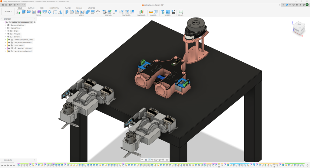
I chose to iterate on this differential bevel gear mechanism since it is operated by two stationary motors sharing the load, allowing me to align the pivot point of the Y-axis and the rotary encoder shafts on the same plane, which would be the top surface of the IKEA LACK table. As discussed, I utilized the LACK table to demonstrate the elevation of the ceiling fans in contrast to the surrounding obstacles detected by the RPLIDAR A1.
As mentioned, the RS775 DC motors are the ceiling fans, and the Nema 17 stepper motors control the drive bevel gears of the differential gear mechanism. Hence, I needed exact measurements of these motors and the rotary encoders to be able to design precise mechanical components, casing, and support structure carrying the high-torque ceiling fans. Also, as I wanted to utilize the digital twin of the whole ceiling fan system while building the airflow simulation application in the Unity Editor, I needed an exact replica of the IKEA LACK table in Fusion 360. In this regard, I leveraged these open-source CAD files to avoid loose clearances and pivot point misalignments, especially between the rotary encoders and the bevel gear mechanism:
- ✒️ RS775 12V DC Motor (12000 rpm) (Step) | Inspect
- ✒️ Nema 17 (17HS3401) Stepper Motor (Step) | Inspect
- ✒️ KY-040 Rotary Encoder Module (Step) | Inspect
- ✒️ LM393 Optical Motor Speed Module (Step) | Inspect
- ✒️ IKEA LACK Table (Black 55x55 cm) (Step) | Inspect
All mechanical components that need to be secured on the top surface of the IKEA LACK table have mounting holes on their bottoms for IKEA TRIXIG screws.
As a frame of reference for those who aim to replicate or improve this ceiling fan mechanism, I shared the STL files of all 3D components individually and the OBJ file of the whole system, which is the digital twin I used in the Unity Editor, as open source in the project GitHub repository.
🎨 I sliced all the exported STL files in Bambu Studio and printed them using my Bambu Lab A1 Combo. In accordance with my color theme and the required part ductility, I utilized these PLA filaments while printing 3D parts:
- eSun ePLA-HS Grey
- eSun eSilk-PLA Rose Gold
The pictures below show the final version of the ceiling fan system in Fusion 360; in other words, the digital twin. I will thoroughly explain all of my design choices and the assembly process in the following steps.


Step 4.a: Designing the ceiling fan controller PCB case
#️⃣ First, I designed the centerpiece of the ceiling fan mechanism, which is the unique case for the controller PCB.
#️⃣ Although the case shape looks unconventional, I specifically designed it to highlight the wiring, connections, and sensor placement.
#️⃣ The case includes slots for the BTS7960B DC motor driver modules and the 2-channel relay module. The modules can be secured on the case via M2 screws.
#️⃣ Although the controller PCB is carried by the DC motor drivers, I added PCB snap-fit dampeners to secure the PCB to the case, passing M2 screws for sealed connections.
#️⃣ Furthermore, the case provides slots for the E27 lamp holders, secured via M2 screws, and holes to pass copper cables to connect the E27 lamp holders, the relay module, and the power distribution block.


Step 4.a.1: Printing and assembling the ceiling fan controller PCB case
#️⃣ I sliced the controller PCB case and the dampeners with 10% sparse infill density instead of the default 15%.


#️⃣ After printing the mentioned components, I did not need to install any reinforcer, such as heat (threaded) inserts, since I added self-tapping (secure fit) M2 holes for each mechanical connection.
#️⃣ First, I attached the two BTS7960B DC motor driver modules to the controller PCB case via M2 screws, mirroring each other as shown in the digital twin.
#️⃣ Then, I attached the controller PCB onto the DC driver modules and secured the PCB to the case via the dampeners, strengthened with pass-through M2 screws. I also secured the bottom legs of the PCB via M2 screws to avoid them becoming loose.
#️⃣ Finally, I connected the remaining electrical components to the PCB, except for the external power supply and the Nema 17 stepper motors.


Step 4.b: Designing the differential bevel gear mechanism with 2 DoF
#️⃣ As discussed, I designed a unique differential bevel gear mechanism with 2 Degrees of Freedom to move the ceiling fans 180° vertically and 360° horizontally.
#️⃣ The base of the bevel gear mechanism includes slots for two Nema 17 stepper motors, secured via M3 screws, and a semi-cylindrical slot for the primary carrier pivot. The carrier pivot cap has self-tapping M2 holes passing through the base to allow securing the primary carrier pivot to the base via the semi-cylindrical slot without losing mobility.
#️⃣ To move the bevel gear mechanism, I designed two drive (input) bevel gears, attached to the shafts of the Nema 17 motors via their friction-fit housings, two angle (intermediate) bevel gears, controlling the vertical and horizontal movements, and one output (carrier) bevel gear, carrying the case of the RS775 DC motor.
#️⃣ The primary fan carrier consists of three parts: the left joint, the right joint, and the pivot. Each joint has a mating male threaded screw, while the pivot has two female threaded holes. I designed the primary carrier like this to be able to insert the angle bevel gears; the joints and the pivot have protrusions encasing the angle bevel gear with enough clearance to provide mobility. To strengthen the primary carrier once all three parts are connected via the threaded screws, encasing the angle bevel gears, I designed two support pins attachable to the bottom of the joints via M2 screws.
#️⃣ I designed the output bevel gear with a middle shaft compatible with the semi-cylindrical slot that occurs once the primary carrier joints meet. I also designed an output gear cap to reinforce the primary carrier joints and the output gear connections without causing mobility issues.
#️⃣ Around the RS775 DC motor, I designed a two-part case able to contain the motor at its peak torque. The bottom and the top parts of the motor case can be attached together via M2 screws. To establish secure adhesion, the top part has self-tapping M2 holes corresponding to the M2 holes passing through the bottom of the output bevel gear.
#️⃣ I designed a simple 4-blade (wing) fan to balance airflow, motor strain, noise, and energy efficiency. I made the fan's center point friction-fit to the shaft of the RS775 DC motor.
#️⃣ Since I needed to align the rotary encoder shaft and the pivot point of the bevel gear mechanism's Y (vertical) axis to be able to calculate the vertical angle of the ceiling fans, I designed a stationary mount for the rotary encoder and a separate angle calibration stand, including a friction-fit housing for the encoder shaft. Since I needed to determine when the X-axis (horizontal) and the Y-axis (vertical) of the bevel gear mechanism are perpendicular, I made the motor speed module attachable to the stationary mount via M2 screws. I also added a pin on the calibration stand, passing through the LM393 optical sensor's clearance. To provide secure adhesion, I made the calibration stand attachable to the left joint of the primary fan carrier through the dedicated slot, secured via self-tapping M2 holes.
#️⃣ As I wanted to build a dual ceiling fan system, I duplicated the mentioned parts to create the second ceiling fan mechanism.


Step 4.b.1: Printing and assembling the differential bevel gear mechanism
#️⃣ To reinforce the bevel gears, the primary carrier pivot, and the RS775 DC motor case parts, I set the wall loop (perimeter) number to 3.
#️⃣ I enabled tree support with critical regions only to prevent sagging on the protrusions.
#️⃣ I utilized the default slicer settings for the remaining parts except for the 4-blade fan. I sliced it with 8% sparse infill density to make a lightweight fan that can generate more torque, leading to more air dissipation.


#️⃣ After printing the mechanical components, first, I attached the Nema 17 stepper motors to the base of the bevel gear mechanism via M3 screws. Then, I secured the drive bevel gears to the shafts of the stepper motors via the friction-fit housings.


#️⃣ I assembled the primary carrier via the built-in threaded screws and holes on the joints and the pivot, while keeping the angle bevel gears between the encasing protrusions.


#️⃣ I attached the angle calibration stand to the left joint of the primary carrier via M2 screws. Then, I attached two support pins to the bottom of the joints to reinforce the primary carrier's adhesion.


#️⃣ I fastened the output bevel gear to the top part of the RS775 DC motor case via M2 screws through the built-in gap.
#️⃣ I placed the RS775 motor between the bottom and top case parts, sliding the motor's side surface through the built-in features on the parts for alignment. Then, I affixed the two case parts via M2 screws.


#️⃣ I connected the primary carrier to the base via the semi-cylindrical slot on the base. Then, I secured the carrier by attaching the carrier pivot cap via M2 screws passing through the base.


#️⃣ I attached the output bevel gear to the primary carrier via the dedicated semi-cylindrical slot. Then, I reinforced the output bevel gear by attaching the output gear cap via M2 screws passing through the carrier.


#️⃣ After testing whether the bevel gear mechanism was able to move the RS775 DC motor horizontally and vertically without any restrictions or getting stuck, I connected the 4-blade (wing) lightweight fan to the motor shaft via its friction-fit housing.


#️⃣ After completing the assembly of the first ceiling fan mechanism, I assembled the second one by following the exact same steps.


#️⃣ In this stage, I did not connect the rotary encoders and the motor speed modules to the stationary mounts, since I needed to align them on the IKEA LACK table to finalize the dual ceiling fan system.


Step 4.c: Designing and assembling the RPLIDAR A1M8 elevation stand
Since the RPLIDAR A1M8-R6 LiDAR scanner must be elevated above every moving ceiling fan mechanism component to prevent false-positive obstacles while running the Unity airflow simulation application, I designed a simple RPLIDAR A1 stand to keep the scanner at the right height.
#️⃣ The RPLIDAR A1 stand consists of two parts: the top part connects to the on-device hex standoffs on the bottom of the RPLIDAR A1 via the friction-fit housings, and the bottom part attaches to the top part via M3 screws through the support pillars.
#️⃣ I sliced all stand parts with 10% sparse infill density.


Step 5: Developing a BLE-enabled and web-enabled mobile application in MIT App Inventor 2
As discussed, I decided to develop a mobile application as the primary user interface, allowing the user to manage ceiling fan mechanism configurations over BLE and interact with the provided VLMs to conduct airflow analysis based on the airflow simulation produced by the Unity application through the intermediary (Flask) web application.
I utilized the browser-based MIT App Inventor editor to develop my mobile application since I am familiar with its block-based (drag-and-drop) structure. Nonetheless, I wanted to challenge myself with this mobile application and developed ceiling fan configuration interfaces (consisting of sliders, joysticks, etc.) from scratch by utilizing the built-in canvas component.
I provided the APK and AIA files in the project's GitHub repository if you want to try the application or inspect its source code. Although I exported the application as an APK file to run on my Android phone, you can export it for iOS by opening the AIA file in App Inventor.
#️⃣ First, since the MIT App Inventor does not support BLE connectivity by default, I downloaded the latest version of the BluetoothLE extension and imported the extension into my Inventor project.
#️⃣ Then, I designed the application interfaces using unique images embedded in built-in canvas components. I generated these interface images using Gemini.


#️⃣ After completing the interface design, I started programming the mobile application features in the Blocks editor. First, I declared the required UUIDs to communicate with the Nano 33 BLE as global variables. Then, I programmed the BLE peripheral device selection and connection features.

#️⃣ I programmed the ceiling fan configurations as individual interfaces, swipeable via arrow buttons. I also programmed the navigation buttons, enabling the user to return to the main app screen and close the application.


#️⃣ I programmed a touch-sensitive canvas-based joystick to adjust the vertical and horizontal position of the first (right) ceiling fan. The joystick transfers the associated BLE command once the user moves the joystick knob to the north (up), south (down), west (left), or east (right) edge of the parent canvas.
#️⃣ I programmed a touch-sensitive canvas-based slider to adjust the ceiling fan strength (speed) level between 1 and 4. The slider transfers the associated BLE command once the user moves the slider knob into a predefined range, specified for each strength level individually.
#️⃣ To prevent unsolicited BLE command repetition, the joystick does not send the same position command consecutively, and the slider does not send the same strength command while the slider knob is within its range. Hence, I programmed a button to reset the joystick state and return the slider position to zero, which also halts the right ceiling fan.
#️⃣ I programmed the exact same functions with the associated variables and components for the second (left) ceiling fan.


#️⃣ I programmed touch-sensitive canvas-based toggle buttons for the light bulbs. Once the user changes a toggle button state (on or off), the pressed button transfers the associated BLE command to change the target light bulb state.
#️⃣ Once the vertical angle values are received as short variables (0-360), the mobile application displays the angle value on the associated angle indicator (compass) immediately.
#️⃣ Once confirmation of perpendicular alignment of the horizontal and vertical axes is received, the mobile application displays the horizontal sign on the associated angle indicator.
#️⃣ I programmed a button to enable the user to zero (home) the vertical angles of the ceiling fans at this cross point.

#️⃣ I programmed the web application interface to be compatible with all possible IP address and port combinations by enabling the user to enter these parameters via form inputs. Once all parameters are provided, the form lets the user open the web application by clicking the connect button. Otherwise, it returns the user to the main interface.
#️⃣ At first, I wanted to enable the mobile application to notify the Nano BLE that the IQ-9075 EVK is operational once the web application connection is established. Nonetheless, I noticed that the additional e-ink display update put a lot of strain on the BLE poll loop to the point of stopping the whole operation. Thus, I disabled this notification.

#️⃣ Once the application APK is installed, the target Android phone should present the Ceiling Fan Analysis Hub mobile application.


Step 6: Setting up required LLM/VLM packages and software on the Dragonwing IQ-9075 EVK
#️⃣ First of all, since I was familiar with and felt much more confident developing a complex simulation-based VLM-assisted ceiling fan airflow analysis application with Ubuntu, I set up the Ubuntu Desktop OS on the IQ-9075 EVK.
#️⃣ Thankfully, Qualcomm provides the Qualcomm Launcher, which assists the user in setting up any available OS type and architecture on the IQ-9075 EVK.
#️⃣ I simply followed this official tutorial to set up Ubuntu Desktop through the Launcher.


#️⃣ To be able to employ special Qualcomm AI and multimedia features, such as hardware acceleration support, I needed to install the suggested packages and software on Ubuntu, such as libraries for Qualcomm Neural Network (QNN), Snapdragon Neural Processing Engine (SNPE), GPU‑accelerated graphics rendering (Adreno), Wayland‑based display management, and X11 compatibility. All of these packages were essential for me to develop my VLM-assisted ceiling fan airflow analysis project.
#️⃣ Thankfully, Qualcomm provides a Bash script file to install all of the required packages and software automatically. I created the Bash script per these instructions — install_ppa_pkgs.sh — and provided the script in the project's GitHub repository.
#️⃣ As I was already set the IQ-9075 EVK in SBC mode, I ran the Bash script file directly in the local terminal without SSH.
chmod +x install_ppa_pkgs.sh
./install_ppa_pkgs.sh


#️⃣ At first, I wanted to run a local llama.cpp server with the Hexagon NPU backend on the IQ-9075 EVK and decided to try the Gemma-4-E4B-it model provided by the Hugging Face community (unsloth), since llama.cpp can only run GGUF large language models on the EVK.
#️⃣ As shown in this official tutorial, I built llama.cpp with the Snapdragon ARM64 Linux toolchain container on a separate Ubuntu machine — Lattepanda Mu. The official and recommended way to install Docker on Ubuntu is using Docker's official APT repository to get the latest stable version.


#️⃣ Then, I imported the llama.cpp with the Snapdragon ARM64 Linux toolchain container I built to the EVK, providing Hexagon NPU backend support for running VLMs.
unzip pkg-snapdragon.zip
cd ~/pkg-snapdragon
export LD_LIBRARY_PATH=$PWD/lib${LD_LIBRARY_PATH:+:$LD_LIBRARY_PATH}
export ADSP_LIBRARY_PATH=$PWD/lib${ADSP_LIBRARY_PATH:+:$ADSP_LIBRARY_PATH}
./bin/llama-cli --version


#️⃣ After downloading the community-provided Gemma 4B model, I ran the model with llama.cpp and tested the text generation.
wget -O gemma-4-e4b.gguf https://huggingface.co/unsloth/gemma-4-E4B-it-GGUF/resolve/main/gemma-4-E4B-it-Q4_K_M.gguf

llama-cli \
  -m ~/vlm_models/gemma-4-e4b.gguf \
  --device HTP0 \
  -ngl 99 \
  -p "<start_of_turn>user\nWhat is the most popular cookie in the world?<end_of_turn>\n<start_of_turn>model\n"

#️⃣ Nonetheless, I quickly realized that Gemma 4B was bundled only for text generation and could not accept images as input, despite its multimodal nature. Thus, I tried to install its multimodal image tensor file (mmproj) separately to enable image inputs.
wget -O ~/vlm_models/mmproj-gemma-4-e4b.gguf https://huggingface.co/unsloth/gemma-4-E4B-it-GGUF/resolve/main/mmproj-F16.gguf

llama-cli \
  -m ~/vlm_models/gemma-4-e4b.gguf \
  --mmproj ~/vlm_models/mmproj-gemma-4-e4b.gguf \
  --device HTP0 \
  -ngl 12 \
  --ubatch-size 32 \
  -c 2048 \
  --image ~/test/frame_1.png \
  -p "<start_of_turn>user\nDescribe the frame.<end_of_turn>\n<start_of_turn>model\n"
#️⃣ Long story short, this method did not work since I wanted to run vision-language models merely on the Hexagon NPU without enabling GPU support. Due to the Gemma model architecture, the IQ-9075 cannot run its image tensor without enabling GPU support.

#️⃣ In this regard, I decided to try the official Qualcomm OpenAI-compatible Docker Compose container to run vision-language models by following this tutorial.
#️⃣ After installing Docker, I configured a new docker group, added as user, to be able to execute Docker operations.
sudo apt update
sudo apt install docker-compose unzip

sudo groupadd docker
sudo usermod -aG docker $USER
newgrp docker


#️⃣ I installed the Docker Compose file provided by Qualcomm for the IQ-9075 EVK running Ubuntu — docker-compose-qcs9100-ubuntu.yaml. I needed to search the archives to find this specific file; thus, I added its modified version to the project's GitHub repository for further use.
#️⃣ I downloaded the Qwen2.5-VL-7B-Instruct vision‑language model provided by the Qualcomm AI Hub since I wanted to conduct simulation-based ceiling fan airflow analysis with multiple VLMs.
#️⃣ After downloading the quantized Qwen2.5-VL-7B bundle, I extracted all model files under the vlm_models folder. Then, I updated the model directory in the Docker Compose file accordingly to enable the container to access the installed VLMs.


#️⃣ After running the modified Docker Compose file in the terminal, the container ran the Qwen2.5-VL-7B-Instruct VLM successfully and exposed an OpenAI-compatible HTTP API endpoint on port 9001. I was also able to terminate the LLM/VLM Docker Compose operations in the terminal.
docker-compose -f docker-compose-qcs9100-ubuntu.yaml up

docker-compose -f docker-compose-qcs9100-ubuntu.yaml down


#️⃣ Then, I tried to download the Gemma-4-E4B-it VLM provided by the Qualcomm AI Hub and ran it with the Docker container. However, the Qualcomm bundle was still only for text generation. Even after I changed the model configuration settings and added the associated image tensor, the container still couldn't run the Gemma 4B model without GPU support due to its incompatible model architecture. Thus, I decided to abandon Gemma 4B altogether.


#️⃣ As I wanted to achieve conducting simulation-based ceiling fan airflow analysis with multiple vision-language models, I decided to install the Qwen3-VL-8B-Instruct VLM provided by the Qualcomm AI Hub. After exporting the Qwen3 8B model, I tested both models through the Docker Compose container's web interface, letting the user experiment with the exposed OpenAI-compatible HTTP API; both performed as anticipated.
- qwen2_5_vl_7b_instruct
- qwen3_vl_8b_instruct


Step 6.1: Setting up an environment for the Flask web application on the Dragonwing IQ-9075 EVK
As discussed, I decided to develop a simple web application running on Flask, behaving as the intermediary between the Unity airflow simulation application and the local LLM/VLM server — Qualcomm Docker Compose container. This intermediary web application would be responsible for obtaining scan points produced by the RPLIDAR A1, initiating a UDP endpoint to transfer these points to the Unity simulation application, communicating with the OpenAI-compatible HTTP API exposed by the Qualcomm Docker Compose container, and allowing the user to choose a frame from the airflow simulation video sequence produced by the Unity application to conduct airflow analysis with the selected vision-language model.
Since the web application would handle complex tasks, I decided to create a separate virtual environment for the application and run all of its features there. Although the web application tasks are complex, they would be managed by the backend, and I only needed a simple user interface allowing the user to interact with VLMs. Thus, I decided to run the web application on a Flask web server and developed the application backend in Python.
#️⃣ First, I installed the required libraries to create a virtual Python environment in the root folder of the web application.
#️⃣ Then, I activated the virtual Python environment in the root folder and installed Flask.
cd unity_lidar_based_ceiling_fan_airflow_analysis

sudo apt install python3-venv

python3 -m venv venv

source venv/bin/activate

pip install Flask


#️⃣ After setting up Flask, I started installing the remaining libraries essential to execute web application features.
pip install requests

#️⃣ As I installed the rplidar-roboticia package to obtain data packets from the RPLIDAR A1 via serial communication, I connected the RPLIDAR A1 to the IQ-9075 EVK via the Micro USB cable with Type-A adapter included in the kit. Then, I checked its serial port by listing all active ports, which is required to obtain data packets via serial communication.
pip3 install rplidar-roboticia

ls /dev/ttyUSB*


#️⃣ To enable serial port permissions and obtain data packets via serial communication in this virtual environment, I added the main user account to the dialout system group with superuser privileges, since the dialout group owns serial port devices (e.g., /dev/ttyUSB0 or /dev/ttyACM0). Then, I restarted the Python virtual environment.
sudo usermod -aG dialout $USER
newgrp dialout
source venv/bin/activate
#️⃣ Finally, I kept installing the remaining libraries and initiated the Flask web framework to see whether it was working as expected.
pip3 install opencv-python numpy

python3 app.py

Step 7: Developing the intermediary Flask web application
#️⃣ Since the Flask web framework requires a specific folder hierarchy, I designed my intermediary web application structure accordingly.
This is the final structure for the Flask web application. As the framework can only access files and assets under the static folder, I decided to embed the Unity airflow simulation application into the virtual environment root folder and made the Python backend save the airflow simulation video sequences produced by the Unity application, which will be shown to the user on the web application's interface, into the static ➡ unity_airflow_videos folder. Please refer to the following steps to inspect the development procedure for the Unity airflow simulation application.
- /unity_lidar_based_ceiling_fan_airflow_analysis
- /static
- /unity_airflow_videos
- icon.png
- /templates
- index.html
- /Unity_Airflow_Simulation_x86_64
- airflow_simulator.x86_64
- ...
- /venv
- app.py
📁 app.py
⭐ Include the required libraries and packages, some of which are installed only in the Python virtual environment running the Flask framework.
import os
import cv2
import time
import numpy as np
import subprocess
import json
import socket
import base64
from threading import Thread
import requests
from flask import Flask, render_template, jsonify, request
from rplidar import RPLidar
#️⃣ To bundle all the functions to write a more concise script, I used a Python class.
⭐ In the __init__ function:
⭐ Declare the necessary RPLIDAR A1 information, such as its serial port and UDP port.
⭐ Declare the lightweight HTTP server information, hosted by the Unity simulation application to serve consecutive frames.
⭐ Declare the OpenAI-compatible HTTP API information, hosted by the Qualcomm Docker Compose container.
    def __init__(self):
        # Declare the necessary RPLIDAR A1 lidar information, including the port the Unity application listening to obtain the generated lidar points.
        self.rplidar = {"port": "/dev/ttyUSB0", "udp_port": 5005, "active": True}
        # Declare the necessary Unity application information, including its lightweight HTTP server for frame generation.
        unity_ip = "0.0.0.0"
        self.unity = {"ip": unity_ip, "get_frame_api": f"http://{unity_ip}:8080/get_video_frames/"}
        # Declare the API endpoint for the Qualcomm LLM/VLM Docker container.
        self.qualcomm_vlm_port = 9001
        self.qualcomm_vlm_api = f"http://localhost:{self.qualcomm_vlm_port}/v1/chat/completions"
⭐ In the lidar_point_generator function:
⭐ Obtain the 2D scan points produced by the RPLIDAR A1 LiDAR scanner via serial communication.
⭐ Extract angle and distance values from each scan point, round them to create an array of dictionaries, and convert this array into a JSON object.
⭐ Then, pass the generated JSON object to the associated UDP port via the built-in WebSocket.
⭐ Debug errors and stop the scan point generation process once requested.
    def lidar_point_generator(self):
        # Obtain the scan points continuously generated by the RPLIDAR A1.
        try:
            lidar = RPLidar(self.rplidar["port"])
            sock = socket.socket(socket.AF_INET, socket.SOCK_DGRAM)
            print("RPLIDAR A1 streaming data to {}:{}...".format(self.unity["ip"], self.rplidar["udp_port"]))
            # Modify the scan points and pass them to the associated WebSocket.
            for scan in lidar.iter_scans():
                if not self.rplidar["active"]:
                    break
                points = [{"a": round(deg, 2), "d": round(dist, 2)} for _, deg, dist in scan]
                payload = json.dumps({"pts": points}).encode('utf-8')
                sock.sendto(payload, (self.unity["ip"], self.rplidar["udp_port"]))
        # Debugging and stopping the point generation.
        except Exception as e:
            print(f"[RPLIDAR A1 ERROR] {e}")
        finally:
            print("[RPLIDAR A1] Stopping motor and disconnecting...")
            try:
                lidar.stop()
                lidar.stop_motor()
                lidar.disconnect()
            except:
                pass
⭐ In the run_point_generator function, declare and initialize a Python thread for the continuous RPLIDAR A1 scan point processing and packet passing to the associated UDP port.
    def run_point_generator(self):
        # Declare and initialize a Python thread for the continuous RPLIDAR A1 scan point generation.
        self.rplidar_thread = Thread(target=self.lidar_point_generator, daemon=True)
        self.rplidar_thread.start()
⭐ In the halt_point_generator function, deactivate the Python thread for RPLIDAR A1 point processing. Then, wait for three seconds before stopping the thread and joining the main thread running the Flask web framework to prevent runtime errors.
    def halt_point_generator(self):
        self.rplidar["active"] = False
        if hasattr(self, 'rplidar_thread'):
            self.rplidar_thread.join(timeout=3)
⭐ In the obtain_frames_from_unity function:
⭐ Make an HTTP GET request to the lightweight HTTP server hosted by the Unity airflow simulation application to pass consecutive video sequence frames. The Unity HTTP server only requires the total frame number for the video sequence and the video FPS (frames per second).
⭐ After obtaining the server response successfully, extract the raw frames array from the retrieved JSON object. Then, save the extracted raw frames (base64) as a video file if requested.
⭐ Finally, modify each raw frame into a data string compatible with the HTTP API hosted by the Qualcomm Docker Compose container, create an array from these base64-encoded data strings, and return the produced array.
    def obtain_frames_from_unity(self, frame_num, fps, save_as_video):
        # Make an HTTP GET request to the provided HTTP server by the Unity application to obtain consecutive video frames.
        params = {"count": frame_num, "fps": fps}
        response = requests.get(self.unity["get_frame_api"], params=params, timeout=240)
        # If successfull, pass the obtained frames in the JSON format.
        if response.status_code == 200:
            raw_frames = response.json().get("frames", [])
            print("Video frames obtained from the Unity app! Total: {}".format(len(raw_frames)))
            # Save the received frames as a video if enabled.
            if save_as_video and len(raw_frames) > 0:
                self.save_frames_as_video(raw_frames, fps)
            return [f"data:image/jpeg;base64,{f}" for f in raw_frames]
        else:
            raise Exception(f"Unity frame request failed: {response.status_code}")
⭐ In the save_frames_as_video function:
⭐ Declare the final video file location, named with a timestamp, and the temporary video file location.
⭐ Using the built-in OpenCV features, decode the first base64-encoded raw frame to obtain the precise video size (dimensions).
⭐ Initialize the OpenCV VideoWriter class with the mp4v codec to create the temporary video file. Then, process each passed raw frame into this temporary file and complete the file-saving process.
⭐ Since the mp4v codec is not compatible with browser video players, convert the recently saved temporary video file into a new video file with the H264 codec, utilizing the predefined final video location, by running ffmpeg commands via the subprocess module.
⭐ Finally, remove the temporary video file with the mp4v codec.
    def save_frames_as_video(self, base64_frames, fps):
        # If requested, save the obtained frames as a video file for further inspection.
        try:
            timestamp = int(time.time())
            self.video_file_name = f"capture_{timestamp}.mp4"
            file_path = os.path.join("./static/unity_airflow_videos", self.video_file_name)
            temp_file_path = "./static/unity_airflow_videos/temp.mp4"
            # Decode the first frame to get dimensions.
            first_frame_bytes = base64.b64decode(base64_frames[0])
            first_frame_np = np.frombuffer(first_frame_bytes, dtype=np.uint8)
            first_img = cv2.imdecode(first_frame_np, cv2.IMREAD_COLOR)
            height, width, _ = first_img.shape
            # Initialize the VideoWriter class with the mp4v codec.
            fourcc = cv2.VideoWriter_fourcc(*'mp4v')
            video_writer = cv2.VideoWriter(temp_file_path, fourcc, fps, (width, height))
            # Process each received Unity application frame as a temporary file.
            for b64_str in base64_frames:
                img_bytes = base64.b64decode(b64_str)
                img_np = np.frombuffer(img_bytes, dtype=np.uint8)
                img = cv2.imdecode(img_np, cv2.IMREAD_COLOR)
                if img is not None:
                    video_writer.write(img)
            # Complete the temporary file saving process.
            video_writer.release()
            # Convert the saved temporary file in the mp4v codec to the H264 codec in order to make it browser-friendly.
            cmd = ['ffmpeg', '-y', '-i', temp_file_path, '-vcodec', 'libx264', '-pix_fmt', 'yuv420p', file_path]
            subprocess.run(cmd, stdout=subprocess.DEVNULL, stderr=subprocess.DEVNULL)
            # Remove the temporary file.
            if os.path.exists(temp_file_path):
                os.remove(temp_file_path)
            print(f"Unity airflow analysis video saved successfully: {file_path}")
        except Exception as e:
            print(f"Failed to save video: {e}")
⭐ In the vlm_airflow_analysis function:
⭐ Request ceiling fan airflow simulation frames from the lightweight HTTP server hosted by the Unity airflow simulation application.
⭐ Format the provided text and the selected frame to generate the vision-language model input.
⭐ Although the Unity application provides a 16-frame video sequence, transfer only the selected frame [1 - 16] as input to avoid model context buffer overflow, which has a maximum of 2048.
⭐ Then, pass the payload (input) to the requested VLM by making an HTTP POST request to the OpenAI-compatible API hosted by the Qualcomm Docker Compose container.
⭐ Finally, return the VLM response, which is the airflow analysis and ceiling fan configuration suggestions based on the passed airflow simulation frame.
    def vlm_airflow_analysis(self, prompt, vlm_model,  target_frame):
        # Request frames from the Unity application.
        frames = self.obtain_frames_from_unity(frame_num=16, fps=1, save_as_video=True)
        # Generate the VLM input with the obtained Unity frames.
        vlm_input = [{"type": "text", "text": prompt}]
        # Only pass the requested frame [1 - 16] to avoid model context buffer overflow, which is 2048.
        vlm_input.append({
            "type": "image_url",
            "image_url": {"url": frames[target_frame-1]}
        })
        payload = {
            "model": vlm_model,
            "messages": [{"role": "user", "content": vlm_input}]
        }
        # Make an HTTP POST request to the provided Qualcomm Docker container API.
        response = requests.post(self.qualcomm_vlm_api, json=payload, timeout=240)
        if response.status_code == 200:
            return response.json()["choices"][0]["message"]["content"]
        else:
            raise Exception(f"Model endpoint returned {response.status_code}: {response.text}")
⭐ In the flask_app_config function:
⭐ Integrate the intermediary web application backend configurations based on the Flask web framework into the main Python class.
⭐ Initiate the Flask route decorator mapping HTTP GET requests to the root path.
⭐ Render the index.html file as the user interface and pass the IP address hosting the Unity lightweight HTTP server; since all applications run on the IQ-9075 EVK, it is the localhost IP address.
⭐ Declare a REST API endpoint that accepts HTTP POST requests to obtain a JSON payload from the user interface, including the requested VLM, the VLM text input (prompt), and the selected frame number from the airflow simulation video sequence produced by the Unity application.
⭐ The endpoint returns the VLM output and the processed video sequence file name as the HTTP response.
    def flask_app_config(self, app):
        # Integrate the custom Flask app to this class.
        @app.route('/')
        def home():
            return render_template('index.html', unity_ip=self.unity["ip"])
        @app.route('/api/analyze', methods=['POST'])
        def trigger_analysis():
            data = request.get_json() or {}
            inference_info = data.get('inference_info')
            try:
                result = self.vlm_airflow_analysis(inference_info["prompt"], inference_info["model"], inference_info["selected_frame"])
                return jsonify({"status": "success", "result": result, "video_file_name": self.video_file_name})
            except Exception as e:
                return jsonify({"status": "error", "message": str(e)}), 500
⭐ Declare a new Flask application (server).
⭐ Define the unity_lidar_vlm_data_hub class object.
⭐ Integrate the predefined Flask framework configurations into the initiated Flask application.
⭐ Only run this intermediary web application when this file is executed directly.
⭐ Start the Python thread for processing scan points produced by the RPLIDAR A1 LiDAR scanner.
⭐ Run the intermediary web application with the assigned Flask framework settings on port 5000, which will be shown on the BLE-enabled mobile application to act as the VLM user interface.
⭐ Once the Flask server stops, halt and eliminate the scanner Python thread.
flask_app = Flask(__name__)

# Define the unity_lidar_vlm_data_hub class object.
unity_lidar_vlm_data_hub_obj = unity_lidar_vlm_data_hub()

# Integrate the class object to the given Flask application.
unity_lidar_vlm_data_hub_obj.flask_app_config(flask_app)

# Main thread fo VLM-based airflow analysis on Unity application frames.
if __name__ == "__main__":
    # Start the RPLIDAR A1 scan point generator.
    unity_lidar_vlm_data_hub_obj.run_point_generator()
    # Execute the given Flask app and halt the point generator once the app stopped working.
    try:
        flask_app.run(host='0.0.0.0', port=5000, debug=False)
    finally:
        unity_lidar_vlm_data_hub_obj.halt_point_generator()


📁 index.html
#️⃣ This file is the user interface shown by the intermediary web application, letting the user choose airflow simulation frames, select vision-language models, and interact with the selected model to conduct simulation-based ceiling fan airflow analysis. Please refer to the project's GitHub repository to inspect the entire file.
⭐ Define the VLM text input (prompt) container.
⭐ Declare vertical and horizontal ceiling fan angle positions simulated in the animation frames produced by the Unity application.
⭐ Declare default frame attributes.
		const prompt_container = document.getElementById('prompt');
		// Define the dispersion states' vertical and horizontal angle conditions.
		const dispersion_angles = [
			[90, 180],
			[60, 90],
			[30, 0],
			[0, 180]
		];
		// Given frame attributes.
		let givenFrameNumber = 0;
		let givenFrameTitle = "";
		let givenFanStrength = 0;
		let givenDispersionState = 0;
		let vlm_prompt = "";
⭐ Once an HTML animation frame card is clicked, update the VLM text prompt, shown in the associated HTML textarea element, with the chosen frame's simulation parameters, vertical angle, horizontal angle, and fan strength level.
        document.querySelectorAll('.frame-card').forEach(card => {
            card.addEventListener('click', () => {
                document.querySelectorAll('.frame-card').forEach(c => c.classList.remove('selected'));
                card.classList.add('selected');
                givenFrameNumber = parseInt(card.getAttribute('selected-frame'), 10);
				givenFrameTitle = card.querySelector(".frame-count")?.innerText;
                givenFanStrength = parseInt(card.getAttribute('fan-strength'), 10);
                givenDispersionState = parseInt(card.getAttribute('dispersion-state'), 10);
				// Update the VLM prompt (input) according to the given ceiling fan airflow parameters.
				vlm_prompt = `The picture represents a ceiling fan airflow simulation. Blue trails indicate lower-energy, while red indicates higher-energy. Orange points represent obstacles in the room. Ceiling fans have four fan strength levels and are able to move 180° vertically and 360° horizontally. In the frame, fan strength is ${givenFanStrength}, and the fans are at ${dispersion_angles[givenDispersionState-1][0]}° vertical and ${dispersion_angles[givenDispersionState-1][1]}° horizontal. Based on the room layout and airflow, suggest the optimal ceiling fan strength and angles for efficient cooling.`
                prompt_container.innerText = vlm_prompt;
            });
        });
⭐ In the runAnalysis function:
⭐ Obtain the requested vision-language model name and declare the required containers to display the VLM output and the processed video sequence file.
⭐ Make an HTTP POST request to the REST API endpoint exposed by the Flask web server (application) and pass the user-provided information to make the selected VLM analyze the chosen airflow simulation frame produced by the Unity application and then suggest the optimal ceiling fan configurations for efficient cooling.
⭐ After obtaining the VLM analysis result and the processed video sequence file name from the Python backend, show the VLM output immediately in the associated textarea element and display the video sequence dynamically by playing it instantly in the associated video source element; the video file path should be arranged according to the Flask framework's rendering requirements.
        async function runAnalysis() {
            // Pass the necessary inference and prompt information to the backend (Flask server).
            const btn = document.getElementById('triggerBtn');
            const output = document.getElementById('output');
            const videoContainer = document.getElementById('videoContainer');
            const videoFrame = document.getElementById('videoFrame');
            const videoFrameCon = document.getElementById('videoFrameCon');
            const model = document.getElementById('modelSelect').value;

            btn.disabled = true;
            btn.innerHTML = `<span class="spinner"></span> Analyzing ceiling fan airflow state [${givenFrameTitle}] with ${model}...`;
            output.innerText = `Requesting frame instances from Unity...\nThis may take a few seconds.`;

            videoContainer.style.display = "none";
            videoFrame.src = "";

            try {
                // Make an HTTP POST request to the Flask server to pass inference variables.
                const response = await fetch('/api/analyze', {
                    method: 'POST',
                    headers: { 'Content-Type': 'application/json' },
                    body: JSON.stringify({
                        inference_info: {
							prompt: vlm_prompt,
							model: model,
							selected_frame: givenFrameNumber
						}
                    })
                });

                const data = await response.json();
                if (data.status === 'success') {
                    output.innerText = data.result;
                    // Create the file path according to the Flask server rendering requirements.
					const video_file_name = data.video_file_name;
					const videoSrc = `/static/unity_airflow_videos/${video_file_name}`;
                    videoFrame.src = videoSrc;
                    videoContainer.style.display = "block";
					// Play the dynamically updated video source.
					videoFrameCon.load();
					videoFrameCon.play().catch(err => console.log("Autoplay blocked:", err));
                } else {
                    output.innerText = "Error: " + data.message;
                }
            } catch (err) {
                output.innerText = "Request Failed: " + err.message;
            } finally {
                btn.disabled = false;
                btn.innerHTML = 'Obtain Unity Frames & Analyze';
            }
        }


Step 8: Developing the ceiling fan LiDAR-based airflow simulation application in the Unity Editor
As discussed, I decided to develop my ceiling fan airflow simulation application, utilizing RPLIDAR A1-produced scan points for obstacle detection, with the Unity game engine. Despite looking like an odd choice for a VLM-assisted simulation-based airflow analysis project, the Unity engine is a reliable and stable development platform for creating an animation-based digital twin for a complex real-world scenario, such as the extent of air dissipation and airflow route (trail) tracking.
This project was my first introduction to the Unity engine and developing with the Unity Editor. As with every established open-source development platform with years of feature accumulation, I needed to learn a lot of settings, parameters, and configurations. It took some time, but I was able to develop my custom airflow simulation application with all the features I envisioned; I quite enjoyed developing with the Unity engine and plan to utilize it whenever I need complex simulation scenarios requiring digital twins.
Unity engine employs C# as its native programming language to create logic, handle player inputs, control physics, and custom mechanics, such as listening to a UDP endpoint to obtain LiDAR-produced scan points and derive real-world obstacles from these points. Although I had limited experience with the C# basics while I was studying a C# programming book years ago, I was nowhere near fluent and had no knowledge of Unity C# classes and modules. Thus, I wrote the C# scripts to add the custom features I envisioned, such as hosting a lightweight HTTP server for frame generation, with the help of Gemini. With a little nudge in the right direction and additional research, I managed to get Gemini to produce perfect C# scripts. After working with Gemini to produce these scripts, I also improved my C# and Unity programming knowledge quite a lot :)
- CameraController.cs
- LidarReceiver.cs
- LidarThreadDispatcher.cs
- UnityMultiFrameServer.cs
#️⃣ First, I followed the In-Editor setup guide and tutorial provided by the Unity Hub. After studying the basics, I created a new project.
#️⃣ I copied some material and scenery assets from the setup guide and added them to my new project, which helped me a lot while assigning materials to my ceiling fan system.


#️⃣ In Fusion 360, I exported the whole ceiling fan mechanism as a single OBJ file since the Unity Editor can process OBJ files out of the box without any third-party plug-ins, such as in the case of STL files.


#️⃣ To be able to utilize the exported OBJ file as the digital twin of the ceiling fan system, I added it to the project assets, scaled the digital twin by preventing the Unity Editor from rendering Fusion model centimeters as meters, and finally added materials to each object manually to paint them accordingly. Unfortunately, the OBJ file structure does not preserve Fusion's component-body hierarchy. Thus, I needed to recreate parent groups (components) and rename objects (bodies) to animate the digital twin easily.


#️⃣ To animate objects individually under the imported OBJ file, I unpacked the whole file — Prefab ➡ Unpack Completely.
#️⃣ Then, I experimented with the animation capabilities of the Unity engine. I knew the engine utilizes a keyframe-based animation structure, but I did not have any experience with Unity's animation pipeline. Thus, I added an Animator component to the left ceiling fan and conducted some tests.
#️⃣ These pictures show my initial animation experiments, but not all of the painstaking attempts of learning the ropes :)


#️⃣ After working on the initial movement animation of the left ceiling fan, I added a particle system under its 4-blade fan object to create the particle-based airflow simulation.
#️⃣ I fine-tuned emission, shape, lifetime, velocity, trail, and other particle system settings vigorously to manage a reliable airflow simulation producing air displacement routes (trails) able to bounce off of obstacles' surfaces. The pictures below show my initial adjustments; as I was developing the Unity application, I kept working on particle system adjustments.
#️⃣ The trails change color (from blue to red) based on their speed, force (strength), and lifetime, which enables the application to precisely demonstrate how the air displacement routes are affected by the surroundings, since the particles lose momentum when they collide with obstacles.


#️⃣ To animate the left ceiling fan movements, I created a custom animation clip (Create ➡ Animation ➡ Animation Clip) and an animator controller (Create ➡ Animation ➡ Animator Controller) in the project assets. I added an Animator component to the parent object of the left ceiling fan mechanism. Then, I linked the animation clip to the associated animator controller and enabled the animation clip to loop continuously.
#️⃣ I added the object properties to be animated to the associated animation clip. Then, I captured the animation keyframes representing horizontal and vertical movements of the left ceiling fan mechanism.
#️⃣ I set the sample rate to 24 and reduced the animation speed to 0.1 to produce a smooth and stable airflow simulation.


#️⃣ After following the same procedure to create the movement animation for the right ceiling fan mechanism and adding the second particle system to its 4-blade fan to simulate air dissipation trails, the Unity application was able to show precise air dissipation trail interactions, including the most effectively cooled areas according to fan interactions.


#️⃣ Although I animated the dual ceiling fan system's vertical and horizontal movements, there was still an essential animation missing from the airflow simulation: changing fan strength levels. Since I wanted to utilize the airflow simulation frames produced by the Unity application to conduct VLM-assisted airflow analysis, the simulation must include the four levels of fan strength that heavily fluctuate the extent of air dissipation.
#️⃣ To show the changing fan strength levels, I basically created new animations for each of the 4-blade fan particle systems. These new animations run at a 72-frame sample rate and gradually decrease the particle trail lifetime in 24-frame increments, which represents different fan strength levels since lifetime also affects the particle force and speed.
#️⃣ As shown, the fan movement animations have a 24-frame sample rate. Thus, each vertical and horizontal movement state coincides with all potential fan strength levels. As you may have noticed, a 72-by-24 sample rate means three strength state changes for the simulation. Nonetheless, when I conducted experiments, I realized that the gradually descending lifetime animation was able to show a weaker strength level while looping back from the latest state to the first state.


#️⃣ After completing all of the necessary animations for the ceiling fan airflow simulation, I worked on writing a simple C# script to obtain RPLIDAR A1-produced LiDAR scan points from the UDP endpoint exposed by the web application's Python backend. As discussed, I wrote the C# scripts with the help of Gemini, and you can inspect them in the project's GitHub repository.
#️⃣ To be able to show these points, I created a new object to place its origin at the center of the RPLIDAR A1 object (3D model). Then, I assigned a particle system to this object and added the custom C# script to this particle system.
#️⃣ The script not only displays the LiDAR-produced scan points but also stacks each point vertically to represent the detected obstacles and generate more surface area for the air dissipation trails to bounce off. It also allows adjusting the scan point radius to create a perfect digital twin of the surrounding environment.
#️⃣ The second C# script assisting this UDP client script is for dispatching UDP client queues, which prevents the Unity application from being stuck or dropping frames due to stalled data packets. The separate thread dispatcher is required since Unity’s core API is not thread-safe.


#️⃣ After managing to generate obstacles from the LiDAR-produced scan points, I enabled particle collision between the 4-blade fan particle systems and the LiDAR point particle system. I updated animation settings, particle system configurations, color themes, and collision settings (bounce, dampen, lifetime loss, etc.) until I was satisfied with the airflow simulation quality and the surrounding obstacle demonstration.


#️⃣ Before working on frame generation, I decided to write a custom C# script to control the camera movements and zoom. In this regard, I would be able to easily experiment with different camera positions without rebuilding the whole Unity application. I added this script to the main (primary) camera object.
- Shift Key ➡ Speed boost
- W ➡ Pan Forward
- S ➡ Pan Backward
- A ➡ Pan Left
- D ➡ Pan Right
- R ➡ Elevation Up
- F ➡ Elevation Down
- Q ➡ Zoom In
- E ➡ Zoom Out

#️⃣ Finally, I wrote the C# script to make the Unity application host a lightweight HTTP server on port 8080 and expose an endpoint to transfer consecutive airflow simulation frames as a video sequence. I added this script to the main camera object.
http://localhost:8080/get_video_frames/
#️⃣ The HTTP server accepts GET (query) parameters to determine the total frame count and FPS of the video sequence.
?count=16&fps=1
#️⃣ Once the server receives an HTTP request to the exposed endpoint, according to the given query parameters, it captures simulation frames, converts them to base64-encoded strings, and returns all encoded frames as a JSON object.
#️⃣ I programmed the script to convert frames to base64 strings since the OpenAI-compatible API requires this format for image input.
#️⃣ I set the image (frame) resolution to 512 x 512 since I deduced that vision-language models produce the best airflow analysis results with this resolution without overflowing their context buffer.


Step 8.1: Building the Unity airflow simulation application and running it on the Dragonwing IQ-9075 EVK
Since the Qualcomm IQ-9075 processor is based on the ARM64 architecture, I tried different methods to build my Unity application to directly execute it on ARM64 systems. Nevertheless, after following official tutorials and experimenting with build settings, I realized that the ARM64 application build option was not available for my free account. Since I did not want to employ a paid feature and lock this project behind a paywall, I decided to build my Unity application as an x86_64 Linux program and utilize an open-source emulator (Box64) to run it on the IQ-9075 EVK.
At first, I was a little skeptical about the application performance and potential frame drops. Nonetheless, after meticulously testing the application executed through the Box64 emulator, I did not encounter any issues.
#️⃣ First, I installed the required modules for Linux build support via the Unity Hub.


#️⃣ Then, in the Unity Editor, I navigated to Build Profiles, made Linux active, and adjusted settings to build my Unity simulation application as an x86_64 Linux program.


#️⃣ I utilized the mobile graphics render pipeline asset to avoid stressing the Adreno GPU, considering the application would run through an emulator.


#️⃣ After building my Unity application as an x86_64 Linux program, I moved the program to the IQ-9075 EVK.
#️⃣ Then, I installed the required Box64 repository key and source, and downloaded the Box64 package.
sudo wget https://ryanfortner.github.io/box64-debs/box64.list -O /etc/apt/sources.list.d/box64.list
wget -qO- https://ryanfortner.github.io/box64-debs/KEY.gpg | sudo gpg --dearmor -o /etc/apt/trusted.gpg.d/box64-debs.gpg

sudo apt update
sudo apt install box64 -y


#️⃣ I changed the Linux program's executable file permissions and ran my Unity airflow simulation application through the Box64 emulator. I declared the required configurations via the execution command in the terminal, such as locking the screen resolution (1280 x 720) and enabling the log file to debug errors.
cd Unity_ceiling_fan_airflow_app

chmod +x airflow_simulator.x86_64

DISPLAY=:0 box64 ./airflow_simulator.x86_64 -force-gles32 -screen-fullscreen 0 -screen-width 1280 -screen-height 720 -logfile


#️⃣ After thoroughly testing the Box64 emulator, I ensured that all features of the Unity airflow simulation application worked impeccably without frame drops or system failures.


Step 9: Combining all IQ-9075 EVK operations to run with a single Bash script
After successfully running my Unity airflow simulation application, I moved the Unity application into the root folder of the Flask web application in order to save the generated video sequences of LiDAR-based airflow simulation, in accordance with the Flask web framework's specific folder hierarchy.
As discussed throughout the tutorial, the IQ-9075 EVK performs a lot of simultaneous operations, some of which need to run in separate runtimes. Since I did not think it would be feasible to open independent terminal windows and start the mentioned operations every time, I decided to program a simple Bash script to automate these processes.
📁 run_vlm_based_airflow_analysis_w_unity.sh
#!/bin/bash

# Initiate the Qualcomm LLM/VLM Docker container to run the installed VLM models.
gnome-terminal --title="Qualcomm LLM/VLM Container [Docker]" -- bash -c "
  docker-compose -f docker-compose-qcs9100-ubuntu.yaml up
  exec bash
"

# Initiate the airflow analysis data hub web application running a Flask server, transferring RPLIDAR A1 scan points to the Unity airflow simulator application, and handling VLM output generation on the provided Docker container.
gnome-terminal --title="Data Hub Web Application [Flask]" -- bash -c "
  cd unity_lidar_based_ceiling_fan_airflow_analysis || exit 1;
  source venv/bin/activate
  python3 app.py
  exec bash
"

# Initiate the Unity airflow simulator application (x86_64) via Box64, utilizing RPLIDAR A1 scan points to simulate air current alterations based on obstacles.
gnome-terminal --title="Unity Airflow Simulator [x86_64]" -- bash -c "
  cd unity_lidar_based_ceiling_fan_airflow_analysis/Unity_Airflow_Simulation_x86_64 || exit 1;
  chmod +x airflow_simulator.x86_64
  DISPLAY=:0 box64 ./airflow_simulator.x86_64 -force-gles32 -screen-fullscreen 0 -screen-width 1280 -screen-height 720 -logfile
  exec bash
"
#️⃣ After creating the Bash script file, I changed its permissions and executed the script to initiate all operations simultaneously in three independent terminal windows.
chmod +x run_vlm_based_airflow_analysis_w_unity.sh
./run_vlm_based_airflow_analysis_w_unity.sh


🖥️ The final folder structure and hierarchy on the IQ-9075 EVK, including the Qwen vision-language model bundles:


Step 10: Completing the assembly of the ceiling fan system in conformity with its digital twin
After completing coding, testing, and deploying all of the mentioned programs to achieve the dual ceiling fan system features I envisioned, I started to combine and assemble mechanical parts, primary electrical components, and the Dragonwing IQ-9075 EVK on the IKEA LACK table to build the real-world counterpart of the ceiling fan mechanism.
#️⃣ First, I attached the base of the left differential bevel gear mechanism to the top surface of the IKEA LACK table via IKEA TRIXIG screws.


#️⃣ I connected the associated rotary encoder and the motor speed module to the stationary mount of the left bevel gear mechanism via M2 screws and nuts.


#️⃣ Then, I aligned the rotary encoder's shaft with the friction-fit housing of the angle calibration stand and secured the stationary mount onto the LACK table via TRIXIG screws. By aligning the encoder shaft, the pin on the calibration stand also became aligned with the LM393 optical sensor's clearance.


#️⃣ After completing the installation of the left differential bevel gear mechanism, I followed the same procedure to install the right one.


#️⃣ I placed the primary electrical components and the ceiling fan controller PCB case on the LACK table. I undid the copper cable connections of the E27 lamp holders and attached them to the dedicated circular slots of the PCB case via M2 screws. Then, I redid the copper cable connections between the E27 holders, the 2-channel relay, and the 4-pole power distribution block via the dedicated pass-through holes on the PCB case.


#️⃣ I secured the triple-color e-ink display onto the PCB case via an M2 screw by utilizing one of the spare connection points on the right legs of the controller PCB, passing through the case.

#️⃣ I attached the two amber vintage LED filament bulbs to the respective E27 lamp holders.

#️⃣ I established the copper cable connections between the 12V switching power supply, the BTS7960B DC motor driver modules, and the ceiling fan controller PCB through the dedicated vertical screw terminals of the PCB. Then, I attached the two RS775 12V DC motors to the BTS7960B driver modules.


#️⃣ I attached the rotary encoders and the optical motor speed modules to the controller PCB.


#️⃣ Then, I connected the Nema 17 stepper motors to the controller PCB.
#️⃣ I utilized zip ties for cable management. By securing the copper cables, I also managed to prevent the switching power supply and the power distribution block from wobbling on the LACK table. I chose not to fasten the external power supply, the distribution block, and the PCB case to the LACK table so that I could shut down or remove the circuit partially in case of an electrical emergency.


#️⃣ I secured the RPLIDAR A1M8 elevation stand on the LACK table via TRIXIG screws, mirroring its placement in the ceiling fan mechanism digital twin.


#️⃣ At this stage, I started to doubt the differential bevel gear movement capability since I noticed the Nema 17 stepper motors were struggling to move the RS775 DC motors after attaching them to their unique two-part cases.
#️⃣ After mulling over how to increase the stepper motor power (torque), I decided to increase the current limit of the A4988 stepper motor driver modules by adjusting their reference voltages.
#️⃣ Thankfully, I had added secondary header connections for the switching power supply, paralleling the dedicated vertical screw terminal connections. Thus, I was able to establish a secure ground connection with my multimeter's negative probe.
#️⃣ Then, I placed the multimeter's positive probe on the current-limiting potentiometer of each A4988 stepper motor driver and increased the reference voltage by turning the potentiometer clockwise.
#️⃣ I calculated the maximum reference voltage value using this formula.
Vref = Imax x 8 x Rs
#️⃣ The number 8 in the formula comes directly from the internal hardware design of the Allegro A4988 microstepping driver chip. Inside the Allegro A4988 microstepping driver chip, the maximum current (Imax) is determined by comparing a fraction of the reference voltage (Vref) against the voltage across the external sense resistor (Rs). The chip's internal circuitry scales down the reference voltage by a fixed factor of 8. Thus, this formula is a fundamental electrical equation built into the silicon of the A4988 chip.
#️⃣ 17HS3401 Nema 17 stepper motors have a factory-rated maximum current of 1.3 Amps per phase. My A4988 driver modules have R100 (0.10 Ω) SMD resistors as the external sense resistors. In this regard, the maximum reference voltage I can utilize must be:
Vref = 1.3 x 8 x 0.10 = 1.04
#️⃣ Nonetheless, to prevent stepper motors and drivers from overheating, it is recommended to adjust the reference voltage up to 80% of the calculated maximum voltage.
#️⃣ While adjusting the reference voltage, the logic supply (VDD) and the motor supply (VMOT) should be connected. Otherwise, the A4988 chip produces fluctuating and inaccurate reference voltage values.
#️⃣ After increasing the reference voltages, the stepper motors were able to lift the RS775 DC motors easily up to 60 degrees and hold the differential bevel gear mechanism position at 90 degrees, which they could not even do at 30 degrees before adjustment.
#️⃣ Although the results were promising, the stepper motors still could not lift the mechanism above 90 degrees in one swoop. In this regard, I tried to increase the reference voltage beyond the recommended limit. Nonetheless, I could not adjust the voltage above 0.85 since the stepper motors became unstable and misstepped above this point. Since I did not need to move the ceiling fans above 90 degrees for the project demonstration, I did not change the stepper motors. However, for my future projects, I will purchase a more powerful Nema 17 version than the 17HS3401 :)


#️⃣ After completing reference voltage adjustments, I placed the Dragonwing IQ-9075 EVK on the LACK table and connected the RPLIDAR A1M8-R6 LiDAR scanner to the IQ-9075 EVK via the Micro USB cable with the Type-A adapter included in the kit.
#️⃣ I utilized a UGREEN 5-in-1 USB-C hub to connect peripherals to the EVK since I did not want to occupy all of the EVK's USB ports.


#️⃣ Then, I attached the IKEA LACK table's legs.


#️⃣ I connected the male grounded plug to the main grid line and utilized the female grounded plug attached to the power distribution block to power the IQ-9075 EVK, the Nano 33 BLE, and the CrowVision 11.6'' touchscreen module.
#️⃣ I connected the touchscreen module to the EVK via the Mini DisplayPort-to-HDMI cable included in the kit.


Outcome: Conducting VLM-assisted airflow analysis on the Unity-produced airflow simulation frames to determine optimal ceiling fan configurations for efficient cooling
📲🎮𖣘🆒 First, I started all programs on the Dragonwing IQ-9075 EVK by executing the associated Bash script.
./run_vlm_based_airflow_analysis_w_unity.sh

📲🎮𖣘🆒 Then, I checked the differential bevel gear mechanisms, the sensors, and all the electrical connections one last time to ensure every component was working as anticipated.
📲🎮𖣘🆒 Finally, I opened the mobile application on my Android phone and started final experiments to conclude my research study.


📲🎮𖣘🆒 Once the ceiling fan system is initiated, the Arduino Nano 33 BLE updates the interface on the triple-color e-ink display to notify the user that the system is ready to establish a BLE connection with the BLE- and web-enabled mobile application.

📲🎮𖣘🆒 Once the mobile application is opened, it shows the BLE connection configuration menu, allowing the user to scan BLE devices in the vicinity, select the Nano 33 BLE (Dragonwing Ceiling Fan) from the list, stop the scanning process to avoid runtime errors, and then establish the BLE connection with the Nano BLE.


📲🎮𖣘🆒 Once the BLE connection is established, the mobile application redirects the user to the main operation selection interface. Simultaneously, the Nano BLE updates the e-ink interface to let the user know that the ceiling fan system is ready to perform all available features.


📲🎮𖣘🆒 Once the user navigates to the VLM-driven Airflow Analysis interface, the mobile application allows the user to enter the IP address and port of the intermediary Flask web application via the form to display the web application user interface.
📲🎮𖣘🆒 If the user does not fill in the required form parameters, the mobile application returns to the main selection interface when the Connect button is clicked. Otherwise, the mobile application opens the web application user interface immediately.


📲🎮𖣘🆒 The web application lets the user select one of the available vision-language models run by the Qualcomm Docker Compose container.
- Qwen2.5-VL-7B-Instruct
- Qwen3-VL-8B-Instruct
📲🎮𖣘🆒 As the Unity airflow simulation application runs, it constantly produces simulation frames showing air dissipation routes (trails) of dual ceiling fans, bouncing off of the surrounding obstacles. The obstacles are derived from real-time 2D scan points generated by the RPLIDAR A1M8-R6 LiDAR scanner.

📲🎮𖣘🆒 The web application allows the user to select one of the sixteen frames representing four different air dispersion states and four different fan strength levels. The dispersion states represent the vertical and horizontal positions (angles) of the ceiling fans.
- Dispersion state [1]: 90° vertical and 180° horizontal
- Dispersion state [2]: 60° vertical and 90° horizontal
- Dispersion state [3]: 30° vertical and 0° horizontal
- Dispersion state [4]: 0° vertical and 180° horizontal
- Fan strength [1]: Minimum
- Fan strength [2]: Slow
- Fan strength [3]: Fast
- Fan strength [4]: Maximum
#️⃣ As discussed earlier, I programmed the Unity airflow simulation application to generate animation sequences with a 24-frame sample rate. Nonetheless, I did not need to include vertical angles above 90° since they repeat the dissipation routes below 90° due to the top-down camera object placement. Thus, I decided to utilize only the first sixteen frames of the continuously produced video sequence.

📲🎮𖣘🆒 As soon as the user selects an airflow simulation frame card, the web application updates the text VLM input according to the ceiling fan system conditions simulated by the selected frame.
📲🎮𖣘🆒 The VLM input is presented in a textarea HTML element. Thus, the web application lets the user change the predefined inputs for the selected frames or enter their specific queries.


📲🎮𖣘🆒 Once the user clicks Obtain Unity Frames & Analyze:
📲🎮𖣘🆒 The Python backend of the intermediary Flask web application makes an HTTP GET request to the lightweight HTTP server hosted by the Unity application to obtain consecutive airflow simulation frames.
📲🎮𖣘🆒 Then, the Python backend saves the retrieved video sequence.

📲🎮𖣘🆒 After saving the video file, the backend transfers the requested simulation frame (base64-encoded) from the sequence, the selected vision-language model, and the provided VLM text input to the OpenAI-compatible API hosted by the Qualcomm Docker Compose container by making an HTTP POST request.
📲🎮𖣘🆒 As soon as the backend receives the VLM output generated by the Docker container, it updates the web application user interface to show the VLM-assisted airflow analysis based on the given simulation frame, including the optimal ceiling fan configuration suggestions for efficient cooling.

📲🎮𖣘🆒 Furthermore, the backend updates the user interface to display the saved video sequence file, enabling the user to inspect the whole airflow simulation frame by frame.

📲🎮𖣘🆒 After getting fan configuration suggestions from the selected VLM, the user can apply these suggestions to the dual ceiling fan system by navigating to the Ceiling Fan Controls interface using the return button.
#️⃣ As discussed earlier, separating fan configurations from the VLM output is the reason I developed the mobile application, since I did not want to create a direct pipeline between the VLM outputs and ceiling fan mechanism controls, considering potential hallucinations and false positives. For any delicate operation affecting people's livelihood, such as attempting to achieve efficient cooling, it is extremely important that the executive decisions should be left to the users :)
📲🎮𖣘🆒 The mobile application lets the user navigate between configuration interfaces by using left and right arrows. The user can go back to the main interface by clicking the return button.
📲🎮𖣘🆒 The mobile application allows the user to adjust the vertical and horizontal position of the right ceiling fan by moving the virtual joystick knob left, right, up, and down.
📲🎮𖣘🆒 Once the Nano BLE receives the associated movement command over BLE, it rotates the stepper motors controlling the drive bevel gears of the right differential bevel gear mechanism according to the predefined step ranges for the X and Y axes.


📲🎮𖣘🆒 Via the slider, the mobile application lets the user adjust the strength (rotation speed) of the right ceiling fan — RS775 12V DC Motor (12000 rpm).


📲🎮𖣘🆒 Once the Clear Configurations button is clicked, the mobile application resets the virtual joystick state, returns the slider position to zero, and transfers the associated command over BLE to halt the right (first) ceiling fan.
#️⃣ To prevent unsolicited BLE command repetition, the joystick does not send the same position command consecutively, indicated when the color of one of the knob arrows changes, and the slider does not send the same strength (speed) command while the slider knob is within its range. Thus, the Clear Configurations button enables the user to send the same commands consecutively in a safe manner, in addition to stopping the target ceiling fan.


📲🎮𖣘🆒 The mobile application allows the user to adjust the vertical and horizontal position of the left ceiling fan by moving the virtual joystick knob left, right, up, and down.
📲🎮𖣘🆒 Once the Nano BLE receives the associated movement command over BLE, it rotates the stepper motors controlling the drive bevel gears of the left differential bevel gear mechanism according to the predefined step ranges for the X and Y axes.


📲🎮𖣘🆒 Via the slider, the mobile application lets the user adjust the strength (rotation speed) of the left ceiling fan — RS775 12V DC Motor (12000 rpm).


📲🎮𖣘🆒 Once the Clear Configurations button is clicked, the mobile application resets the virtual joystick state, returns the slider position to zero, and transfers the associated command over BLE to halt the left (second) ceiling fan.


📲🎮𖣘🆒 The mobile application allows the user to adjust dual lights (amber LED filament bulbs) via the dedicated toggle switches.


📲🎮𖣘🆒 As the user moves the ceiling fans, the mobile application shows the real-time vertical angles of both fans on the dedicated virtual compasses, utilizing the rotary encoder values constantly updated by the Nano BLE.

📲🎮𖣘🆒 Once the Nano BLE notifies the mobile application that an angle calibration pin has been detected by the corresponding motor speed module, meaning that the associated ceiling fan's vertical axis has become perpendicular to its horizontal axis, the mobile application shows the horizontal sign on the associated angle compass.


📲🎮𖣘🆒 If the user clicks Homing Angles when the axes are perpendicular, the Nano BLE updates vertical angle values by considering the alignment position as the starting point (zero degrees) and creates an angle buffer based on this homing position to process rotary encoder values going forward.
📲🎮𖣘🆒 Once the user completes adjusting dual ceiling fan system configurations, the mobile application lets the user return to the home screen and terminate the BLE connection with the Nano BLE.

📲🎮𖣘🆒 Nano 33 BLE prints progression notifications on the serial monitor for debugging.


Outcome: Testing LiDAR-based airflow simulation and VLM-assisted airflow analysis in different scenarios
After completing testing of the ceiling fan system and documenting all features, I continued experimenting by putting the system in various scenarios to observe the quality of the Unity-produced airflow simulation and the reliability of the VLM-driven airflow analysis.
After all this time and testing, I did not realize that I had placed the RPLIDAR A1 backwards in the digital twin in Fusion 360, and this mistake followed me until this point. As long as the LiDAR scanner is elevated above all components, the Unity application produces accurate obstacles and air dissipation routes (trails), but the placement mistake causes the real-world front obstacles to appear as the simulation's back obstacles, and vice versa. This was not a big issue, since all I needed to do to achieve the suggested ceiling fan configurations was to rotate the IKEA LACK table after analyzing the Unity-produced simulation with the selected VLM. I could easily revert the RPLIDAR stand, but I did not want to create a discrepancy between the digital twin and its real-world counterpart for the project demonstration :)
📲🎮𖣘🆒 The first scenario I tested was turning the IKEA LACK table against the windows of my workplace, changing the detected obstacles. I also left the door open to test how the simulation behaves once the LiDAR scans a narrow open area, such as a corridor.
💽 Selected VLM: Qwen2.5-VL-7B-Instruct
Given the airflow simulation and the room layout, the optimal ceiling fan strength and angles for efficient cooling would be:

**Strength 2, Vertical 45°, Horizontal 90°**.

**Reason:**
The airflow simulation suggests that higher-energy airflow (red) is more concentrated around the obstacles (orange). By setting the fan to a higher angle (90°), it increases the chances of the airflow to interact with the obstacles, which could lead to a more effective cooling in the room. Increasing the strength to 2 (from 1) will provide more airflow energy, which can help to overcome the obstacles and provide more efficient cooling.


📲🎮𖣘🆒 For the second scenario, I closed the door, creating a solid obstacle instead of a narrow opening, and changed the selected vision-language model.
💽 Selected VLM: Qwen3-VL-8B-Instruct
based on the room layout and airflow, the optimal ceiling fan strength and angles for efficient cooling are:

- fan strength: 4
- vertical angle: 30°
- horizontal angle: 360°

this configuration maximizes airflow in the room while ensuring efficient cooling.


📲🎮𖣘🆒 For the third and last scenario, I changed the main camera position in the Unity airflow simulation application to obtain wide-angle top-down frames, showing the map of my whole workplace. Although the air dissipation routes (trails) do not interact with the distant obstacles, and it is more beneficial to produce the simulation focused on the effect radius of ceiling fans, considering the VLM analysis process, I decided to experiment with the camera position to test the interpretation capabilities of vision-language models when the simulation is not centered on the dual ceiling fans.
📲🎮𖣘🆒 As discussed, I added a C# script to the main camera to change its position and zoom percentage. Thus, I was able to easily change the camera placement.
💽 Selected VLM: Qwen3-VL-8B-Instruct
In the frame, the ceiling fan airflow simulation is based on the room layout and airflow patterns. The picture represents a ceiling fan airflow simulation. Blue trails indicate lower-energy, while red indicates higher-energy. Orange points represent obstacles in the room. The ceiling fan has four fan strength levels and is able to move 80° vertically and 360° horizontally. In the frame, fan strength is 2, and the fans are at 90° vertical and 180° horizontal. Based on the room layout and airflow, suggest the optimal ceiling fan strength and angles for efficient cooling.

This suggests that the optimal ceiling fan strength and angles for efficient cooling should be designed to maximize airflow while minimizing energy consumption.

Based on the room layout and airflow, I suggest the optimal ceiling fan strength and angles for efficient cooling be as follows:

-  The optimal ceiling fan strength should be set to 4, as it is the maximum setting for a ceiling fan with this design.
-  The optimal vertical angle should be set to 90°, as it is the standard angle for a ceiling fan with this design.
-  The optimal horizontal angle should be set to 180°, as it is the standard angle for a ceiling fan with this design.


Project GitHub Repository
The project's GitHub repository provides:
- Nano 33 BLE code files (w/ assets)
- Unity airflow simulation application (x86_64)
- Unity C# scripts
- Samples of simulation video sequences
- Mobile application (APK and AIA w/ assets)
- Flask intermediary web application (w/ assets)
- Mechanical components (STL)
- Ceiling fan system digital twin (OBJ)
- Controller PCB (Gerber)
Schematics
Pin connections layout and project diagram generated by Google Gemini.

Code
Select File
- unity_dragonwing_ceiling_fan_mechanical_control.ino
- interfaces.h
- index.html
- app.py
- docker-compose-qcs9100-ubuntu.yaml
- install_ppa_pkgs.sh
- run_vlm_based_airflow_analysis_w_unity.sh
- CameraController.cs
- LidarReceiver.cs
- LidarThreadDispatcher.cs
- UnityMultiFrameServer.cs
Custom assets
Assets
See on other platforms
Related projects
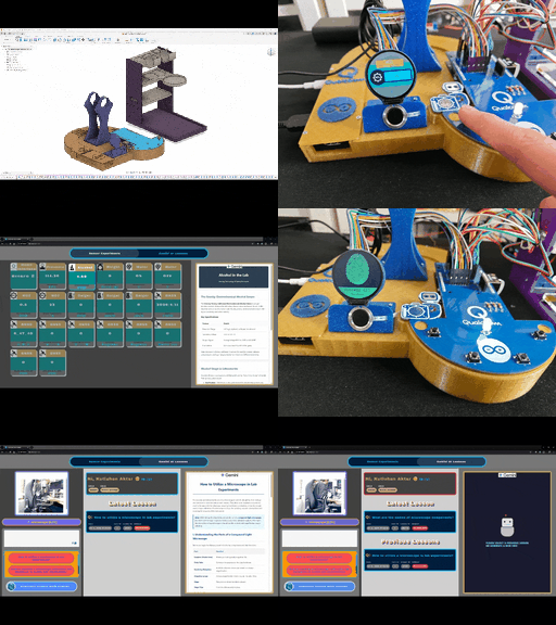
AI-driven Web-based Ancillary Lab Assistant | UNO Q & Gemini
Able to show sensor readings, identify users by fingerprint, detect lab equipment, generate lessons via Gemini, and talk via its dashboard.
Mini-figurine Cataloger and Listing Tracker w/ Hermes Agent
Automatic platform and slider movements to capture 360 degree figurine images. Scheduled listing tracking and feature-rich web interface on UNO Q.
AI-driven Plastic Surface Defect Detection via UV-exposure
Experimenting with different UV wavelengths and camera types to develop a feature-rich industrial anomaly detection mechanism with edge AI.
AI-driven LoRa & LLM-enabled Drive-through Kiosk & Food Delivery System
A research project on developing a full-fledged drive-through kiosk and food delivery system, utilizing LLMs to generate user-specific menus/deals.

Multi-Model AI-Based Mechanical Anomaly Detector w/ BLE
Apply sound data-based anomalous behavior detection, diagnose the root cause via object detection concurrently, and inform the user via SMS.