


AI-driven Web-based Ancillary Lab Assistant | UNO Q & Gemini
May 10, 2026


Navigation Bar
Apply Theme
- Introduction
- Keywords
- Brands
- Hardware
- Software
- Description
- Development process, thinking in terms of creating an Arduino App Lab application, and final results
- Step 0: Integration and use cases of Google Gemini
- Step 1: Configuring initial Arduino App Lab settings and determining suitable sensors for the ancillary lab assistant
- Step 1.1: Adding and revising the sketch libraries to make the target sensors compatible with the UNO Q
- Step 2: Programming the Arduino sketch executed by the STM32U585 (MCU)
- Step 3: Collecting images of different lab equipment to construct a valid data set
- Step 4: Building an object detection model (FOMO) w/ Edge Impulse Enterprise
- Step 4.1: Uploading and labeling the lab equipment image samples
- Step 4.2: Training the FOMO object detection model
- Step 4.3: Evaluating the model accuracy and deploying the validated model
- Step 5: Adding and adjusting the necessary Bricks to develop a feature-rich lab assistant application on the App Lab
- Step 6: Programming the Python script (backend) executed by the Qualcomm QRB2210 microprocessor (MPU)
- Step 7: Developing a full-fledged lab assistant web dashboard hosted directly by the Arduino App Lab
- Step 7.1: Ensuring the lab assistant App Lab application operates as anticipated to enable easy importing for further research cases
- Step 7.2: Timeout issues with the latest Zephyr platform release (0.54.1)
- Step 7.3: Continuing issues with the most recent Zephyr platform (0.55.0)
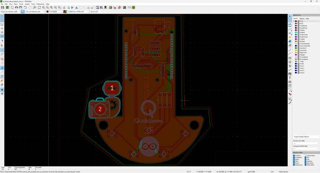
- Step 8: Designing the lab assistant analog interface PCB as an Arduino UNO Q shield (hat)
- Step 8.1: Soldering and assembling the lab assistant analog interface PCB
- Step 9: Modeling the ancillary lab assistant 3D components to form the final device structure
- Step 9.a: Designing the base of the ancillary lab assistant
- Step 9.a.1: Printing and assembling the assistant base
- Step 9.b: Designing the experiment-ready modular lab assistant sensor ladder
- Step 9.b.1: Printing and assembling the lab assistant sensor ladder
- Step 9.c: Final adjustments and installing the analog interface PCB
- Outcomes: Conducting LLM-assisted lab experiments with the integrated lab sensors
- Outcomes: Identifying lab equipment via object detection and generating distinctive AI lessons about them via Google Gemini
- Project GitHub Repository
- Schematics
- Code
- Custom assets
- See on other platforms
- Related projects
Based on Arduino UNO Q, this lab assistant is able to show real-time sensor readings, identify users by fingerprint, recognize lab equipment via object detection, generate AI lessons via Gemini, and talk through its full-fledged web dashboard.
Keywords
Hardware
- 1Arduino UNO Q 4GB
- 1UGREEN 5-in-1 100W USB-C Hub with 4K@60Hz HDMI and 3 * USB-A 3.0
- 1A4 Tech PK-910H USB Webcam (1080p)
- 1Raspberry Pi 15W 5.1V / 3.0A USB-C Power Supply
- 1Custom PCB
- 1DFRobot Capacitive Fingerprint Sensor (UART)
- 1DFRobot Gravity: Electrochemical Alcohol Sensor
- 1DFRobot Gravity: 1Kg Weight Sensor Kit - HX711
- 1DFRobot Gravity: Geiger Counter Module
- 1DFRobot Gravity: Electrochemical Nitrogen Dioxide Sensor
- 1Seeed Studio Grove: Integrated Pressure Sensor Kit (MPX5700AP)
- 1Seeed Studio Grove: Water Atomization Sensor (Ultrasonic)
- 1DFRobot Gravity: GNSS Positioning Module
- 1Waveshare 1.28" Round LCD Display Module (GC9A01)
- 4Button (6x6)
- 15 mm Common Anode RGB LED
- 3220Ω Resistor
- 160 mm Petri Dish
- 1M2 Screws, Nuts, and Washers
- 1USB Buck-Boost Converter Board
- 1Jumper Wires
- 1Bambu Lab A1 Combo
Software
Description
After hearing about the launch of the brand-new Arduino UNO Q, designed as the first SBC (single-board computer) with Arduino's philosophy of bridging the gap between employing professional development tools and implementing them as novices when creating introductory projects or as experts while prototyping complex mechanisms rapidly yet stably, I thought it would be a great opportunity to redesign my previous AI-driven lab assistant project and enable more developers, beginner or expert, to replicate, experiment, or improve this new AI-based ancillary lab assistant thanks to the built-in Arduino UNO Q features and its beginner-friendly development platform — Arduino App Lab.
As you may know, if you have read one of my previous project tutorials, I prefer building my AIoT projects on the target development boards and environments from scratch and enjoy developing unique methods, applications, and mechanisms to collect custom training data and achieve intended device features, strictly following my methodology of developing proof-of-concept research projects. Nonetheless, in this project, I heavily focused on developing all lab assistant features based on the provided UNO Q and Arduino App Lab characteristics, such as the built-in Bricks, native microprocessor-microcontroller communication procedure, and Linux-oriented SBC board architecture, to ensure that anyone with a UNO Q can effortlessly replicate and examine this lab assistant without needing to have a deep understanding of all aspects of this project; coding, web design, neural network training, LLM-implementation, 3D modeling, etc. In this regard, I hope this project serves as an entry point for developing research projects, encouraging readers to reverse-engineer the features of this AI-driven lab assistant to gain a deeper understanding of AIoT development on the edge.
As I was taking inspiration from my previous lab assistant project, I heavily modified the device structure and added a lot of new features specific to this iteration, for instance, designing a unique PCB (UNO Q shield) for utilizing various lab sensors to conduct LLM-assisted basic lab experiments. After months of hard work, I managed to complete the reimagined AI-driven ancillary lab assistant structure and develop all the features I envisioned on UNO Q by solely employing the Arduino App Lab development environment, providing foundational building blocks (Bricks).
🤖 To build the ancillary lab assistant structure:
✍🏻 I designed a unique PCB as a UNO Q shield (hat) to connect the selected lab sensors and create the analog lab assistant interface, including the capacitive fingerprint sensor.
✍🏻 Then, I modeled 3D parts to design the ancillary lab assistant base, containing the USB camera and the analog interface.
✍🏻 Finally, I designed a modular lab sensor ladder, organizing all sensors and secondary experiment tools, to create a compact but easy-to-use instrument.
🤖 To accomplish all of the ancillary lab assistant features I contemplated, performed by an Arduino App Lab application:
🛠️ I trained an Edge Impulse object detection model to identify various lab equipment.
🛠️ I programmed the MCU (STM32) to collect real-time sensor information and manage the analog lab assistant interface.
🛠️ I developed a feature-rich web dashboard as the primary user interface and control panel of the lab assistant, hosted directly by the Arduino App Lab.
🛠️ I incorporated Google Gemini to enable the lab assistant to generate LLM-based lessons about the detected lab equipment.
🛠️ Thanks to the built-in background Linux MPU-MCU communication service (Arduino Router), I built the interconnected interface background in Python, handling the data transfer between the web dashboard, the analog interface (MCU), and the Qualcomm QRB (MPU) running the essential App Lab Bricks (Docker containers); database registration, inference running, web dashboard (UI) hosting, etc.
🤖 The finalized ancillary lab assistant allows users to:
🔬 create web dashboard accounts and sign in via fingerprint authentication,
🔬 monitor real-time lab sensor readings via the analog interface or the web dashboard,
🔬 inspect LLM-generated sensor guides and experiment tips for each lab sensor via the web dashboard,
🔬 capitalizing on the built-in browser text-to-speech (TTS) module, listen to LLM-generated sensor guides and experiment tips,
🔬 identify lab equipment via the provided Edge Impulse FOMO object detection model,
🔬 use the predefined equipment questions or enter a specific one to generate AI lessons through Google Gemini,
🔬 access the list of LLM-generated lessons assigned to your account on the web dashboard anytime,
🔬 study LLM-generated lessons by reading or listen to them via the TTS module.
🎁 📢 Although I did not utilize any service or product specifically sponsored for this project, I send my kind regards to DFRobot and Seeed Studio since some of the sensors were sponsored by them for my previous projects :)


Development process, thinking in terms of creating an Arduino App Lab application, and final results
As mentioned in the introduction, the development process of this AI-driven lab assistant differs quite a bit from my previous AIoT projects since I built a single application within the confines of the Arduino App Lab development environment, specifically constructed to capitalize on the dual-brain (MPU-MCU) nature of UNO Q, even though I developed a feature-rich web dashboard and analog lab assistant interface individually. Arduino App Lab provides built-in Bricks (Docker containers) for adding various fundamental attributes to an App Lab application, such as web UI hosting, inference running for custom models, etc., and manages all of the operations of the included Bricks while executing the completed application. Thus, although I still utilized specific programming languages to develop the different aspects of the lab assistant App Lab application, Arduino for programming the STM32 microcontroller (MCU), Python for the application backend (Qualcomm MPU), and HTML, CSS, JavaScript for the web dashboard, as a whole, I built a single application that the App Lab runs and manages.
I think the most prominent feature of UNO Q, with the support of the App Lab, is the built-in RPC (Remote Procedure Call) managed by the Arduino Router background Linux service, which enables developers to borrow and run functions between Qualcomm MPU and STM32 MCU interchangeably. App Lab also provides a built-in web socket to establish data transfer between the web dashboard and the Python backend. In this regard, it makes the communication between the STM32 MCU and the web dashboard effortless through the same Python backend. In light of these built-in features, I decided to build the second iteration of my AI-driven lab assistant with UNO Q.
Generally, I thoroughly explain the setup process of my interconnected software and hardware applications according to the employed development boards, modules, environments, third-party APIs, etc. However, since I only utilized the built-in Arduino App Lab attributes to enable anyone with a UNO Q to replicate and examine this project effortlessly, I highly recommend inspecting the official Arduino UNO Q specifications and tutorials.

To be able to use UNO Q as a single-board computer and connect a USB camera, I needed to use a USB-C hub (dongle) with reliable HDMI, USB-A, and USB-C external power ports. Nonetheless, since UNO Q does not have a dedicated GPU, the processing power was too slow to run the App Lab and develop the lab assistant application solely in the SBC mode, especially the web dashboard. Thus, I utilized the SBC mode and the network mode simultaneously, supported by the App Lab, to access UNO Q remotely on any machine connected to the local network. In this regard, I was able to build the lab assistant App Lab application by accessing the full capacity of the Arduino App Lab.
#️⃣ Since I needed to capture screenshots for this tutorial while utilizing the SBC mode, I installed a simple program to enable taking screenshots on Debian-based Linux distributions via the terminal.
sudo apt install xfce4-screenshooter

I documented the overall development process for the finalized ancillary lab assistant in the following written tutorial. Even though I exhibited all of the lab assistant features in the tutorial, I highly recommend checking the project demonstration videos that thoroughly showcase the device structure and real-time user experience of the analog assistant interface and the web dashboard.
Step 0: Integration and use cases of Google Gemini
Since I wanted users to generate AI lessons based on questions about specific lab equipment and inspect the LLM-generated lessons via the web dashboard, I decided to fine-tune the large language model responses appropriately to obtain lessons directly in the HTML format. According to my previous experiments with different large language models that I conducted while developing LLM-oriented projects, Google Gemini produced reliable, informative, and concise HTML pages about simple inquiries. Thus, I decided to utilize Google Gemini to enable the ancillary lab assistant to produce AI lessons. Furthermore, Google Gemini has a very low barrier to entry for utilizing its primary chat application and API services.
#️⃣ First, to be able to integrate Google Gemini into my Arduino App Lab application, I opened Google AI Studio and created a new API key specific to this project.
#️⃣ Since the App Lab already provides a Brick to integrate and use cloud LLMs in Python, I only needed to register the produced API key into my custom application. I will explain how to utilize Bricks in detail in the following steps.


#️⃣ Although I enabled users to produce AI lessons freely on different lab equipment based on predefined or specific questions, I decided to make the web dashboard present LLM-generated but curated guides with simple experiment tips about the selected lab sensors. To ensure the consistency between the user-generated AI lessons and the static (default) lab sensor guides with experiment tips, I employed the official Google Gemini chat application to produce dedicated HTML pages for each lab sensor.
❓ Such as: "Create me an HTML page explaining Gravity: Factory Calibrated Electrochemical Alcohol Sensor and the importance, dangers, and usage of alcohol in labs."
#️⃣ Since I am not a talented graphic or logo designer, I also decided to employ Gemini to produce custom logos and CSS animations for the web dashboard. I specifically made Gemini to contain each CSS animation in a separate HTML page, which helped me to manage my primary web dashboard layout and Gemini-generated elements. For each Gemini-generated static lab sensor information page, animation page, and logos (images), I added the gemini moniker to their file names.
- gemini_alcohol_concentration.html
- gemini_fingerprint_waiting.html
- gemini_text_to_speech_stop_logo.png


Step 1: Configuring initial Arduino App Lab settings and determining suitable sensors for the ancillary lab assistant
Since Arduino UNO Q comes with the Arduino App Lab installed out of the box, I did not need to take any additional steps to run the App Lab in the SBC mode other than upgrading the Debian Linux operating system and the App Lab to their latest versions. However, to be able to utilize the network mode to program the lab assistant App Lab application remotely, I downloaded the Arduino App Lab on my workstation.
#️⃣ First, I connected a compatible USB dongle (hub), UGREEN 5-in-1, to the UNO Q in order to upgrade the Debian operating system and the Arduino App Lab.

#️⃣ After downloading the Arduino App Lab on my workstation, I created a new App Lab application to start developing my custom lab assistant application.


#️⃣ After successfully creating my lab assistant App Lab application, I meticulously searched for the most feasible lab sensors to enhance my ancillary lab assistant. As I have worked on multiple experimental research projects, I have had the chance to choose lab sensors from my ever-growing arsenal.
#️⃣ After selecting suitable sensors from my collection, I also added new ones to enable the ancillary lab assistant to provide a wide range of lab experiment options.
- Gravity: Electrochemical Alcohol Sensor | Guide
- Gravity: 1Kg Weight Sensor Kit - HX711 | Guide
- Gravity: Geiger Counter Module | Guide
- Gravity: Electrochemical Nitrogen Dioxide Sensor | Guide
- Grove: Integrated Pressure Sensor Kit (MPX5700AP) | Guide
- Grove: Water Atomization Sensor (Ultrasonic) | Guide
- Gravity: GNSS Positioning Module | Guide
#️⃣ As mentioned earlier, I decided to build an analog assistant interface to enable observing real-time sensor readings manually and activating web dashboard accounts via fingerprint authentication. Thus, I also connected these components to the UNO Q.
- DFRobot Capacitive Fingerprint Sensor (UART) | Guide
- Waveshare 1.28" Round LCD Display Module (GC9A01) | Guide
#️⃣ Although UNO Q comes with 3.3V and 5V power lines, since it would not be feasible to supply power to all these current-heavy components directly from the UNO Q, I utilized a buck-boost converter to supply all components requiring 3.3V via an external power source.
#️⃣ Since the pinout and dimensions of the Arduino UNO Q are equivalent to the standard Arduino Uno's, connecting all components was straightforward.
// Connections
// Arduino UNO Q :
//                                Capacitive Fingerprint Sensor (UART)
// 3.3V    ------------------------ VIN
// GND     ------------------------ GND
// D1 / USART1_TX ----------------- RX
// D0 / USART1_RX ----------------- TX
// 3.3V    ------------------------ 3V3
//                                Gravity: Electrochemical Alcohol Sensor
// 3.3V    ------------------------ +
// GND     ------------------------ -
// SCL     ------------------------ C/R
// SDA     ------------------------ D/T
//                                Gravity: 1Kg Weight Sensor Kit - HX711
// 3.3V    ------------------------ VCC
// GND     ------------------------ GND
// SCL     ------------------------ SCL
// SDA     ------------------------ SDA
//                                Gravity: Geiger Counter Module - Ionizing Radiation Detector
// GND     ------------------------ -
// 3.3V    ------------------------ +
// D2      ------------------------ D
//                                Gravity: Electrochemical Nitrogen Dioxide Sensor - NO2
// 3.3V    ------------------------ +
// GND     ------------------------ -
// SCL     ------------------------ C/R
// SDA     ------------------------ D/T
//                                Grove - Integrated Pressure Sensor Kit - MPX5700AP
// GND     ------------------------ GND
// 3.3V    ------------------------ VCC
// A0      ------------------------ SIG
//                                Grove - Water Atomization Sensor - Ultrasonic
// GND     ------------------------ GND
// 5V      ------------------------ VCC
// D4      ------------------------ EN
//                                Gravity: GNSS Positioning Module
// 3.3V    ------------------------ +
// GND     ------------------------ -
// SCL     ------------------------ C/R
// SDA     ------------------------ D/T
//                                Waveshare - 1.28inch Round LCD Display Module
// 3.3V    ------------------------ VCC
// GND     ------------------------ GND
// D11     ------------------------ DIN
// D13     ------------------------ CLK
// D10     ------------------------ CS
// D7      ------------------------ DC
// D8      ------------------------ RST
// D9      ------------------------ BL
//                                Control Button (A)
// A1      ------------------------ +
//                                Control Button (B)
// A2      ------------------------ +
//                                Control Button (C)
// A3      ------------------------ +
//                                Control Button (D)
// A4      ------------------------ +
//                                5mm Common Anode RGB LED
// D3      ------------------------ R
// D5      ------------------------ G
// D6      ------------------------ B
#️⃣ To enable the ancillary lab assistant to identify specific lab equipment via object detection, I attached a USB camera (PK-910H) to the UNO Q through the USB dongle (hub).
#️⃣ As I already had a spare one, I used an official Raspberry Pi 5.1V / 3.0A USB-C power supply to power the UNO Q through the USB hub. Nonetheless, you can use any power supply compatible with the UNO Q specifications.


Step 1.1: Adding and revising the sketch libraries to make the target sensors compatible with the UNO Q
Even though Arduino UNO Q shares the same layout with the standard Arduino Uno, the MCU structure (STM32) and the bootloader (which runs on the Zephyr RTOS) are completely different. Thus, I needed to add component libraries that were not present in the provided App Lab library collection and heavily modify most of the component libraries to make them compatible with the UNO Q structure.
#️⃣ First, I added sketch libraries available in the provided App Lab library collection, including the MessagePack (msgpack) library, which is essential to utilize the Arduino Router service on the MCU.


#️⃣ Then, I created a folder named customLibs under the lab assistant application's sketch folder and installed libraries that were not present in the provided library collection.
#️⃣ To enable the App Lab to access the custom libraries, I edited the sketch.yaml file accordingly via the default command-line text editor (GNU nano).
- dir: customLibs/<lib_name>
- dir: customLibs/DFRobot_MultiGasSensor


#️⃣ There were a plethora of sketch library incompatibilities and errors, especially with lab sensor libraries. For each error, I pinpointed the faulty code and deliberately modified files via the GNU nano text editor.
#️⃣ As the Arduino App Lab does not share sketch libraries like the Arduino IDE, since each App Lab application is a single Docker project, I needed to target the assigned library paths for the lab assistant App Lab application while editing files installed directly by the App Lab. In the case of the App Lab creating folder names with spaces, I enclosed the path with quotes (") on the terminal to access the required files. Conversely, revising the custom libraries I added under the customLibs folder via the terminal was straightforward.
sudo nano /home/arduino/.arduino15/internal/<target_library>/<target_file>
sudo nano /home/arduino/.arduino15/internal/DFRobot_HX711_I2C_1.0.0_d8304db78735c6a3/DFRobot_HX711_I2C/DFRobot_HX711_I2C.h


#️⃣ After installing different library versions, modifying them, and making sure each component works as intended, I copied all the libraries I modified from the internal App Lab sketch library folder and added them to my custom libraries under the customLibs folder.
- dir: customLibs/modded_Adafruit_GC9A01A_1.1.1
- dir: customLibs/modded_DFRobot_Alcohol_1.0.0
#️⃣ I decided to save nearly all sketch libraries locally to ensure that the lab assistant App Lab application works without any additional code or library modification once imported via the provided ZIP folder. You can inspect the project GitHub repository to inspect all code files and download the ZIP folder.


Step 2: Programming the Arduino sketch executed by the STM32U585 (MCU)
📁 logo.h
To prepare monochromatic images in order to display custom logos on the round LCD module (GC9A01), I followed the process below.
#️⃣ First, I converted monochromatic bitmaps to compatible C data arrays by utilizing LCD Assistant.
#️⃣ Based on the round display type, I selected the Horizontal byte orientation.
#️⃣ After converting all logos successfully, I created this header file — logo.h — to store them.


📁 color_theme.h
#️⃣ In this header file, I assigned global HEX variables (compatible with the Adafruit GFX library) to create the primary color theme for the analog lab assistant interface.

📁 sketch.ino
⭐ Include the required sketch libraries.
#include <Arduino_RouterBridge.h>
#include <DFRobot_ID809.h>
#include "DFRobot_Alcohol.h"
#include <DFRobot_HX711_I2C.h>
#include "DFRobot_MultiGasSensor.h"
#include <DFRobot_Geiger.h>
#include "DFRobot_GNSS.h"
#include "SPI.h"
#include "Adafruit_GFX.h"
#include "Adafruit_GC9A01A.h"
⭐ Import custom logos (C data arrays) and the provided HEX color variables.
#include "logo.h"

// Import the custom color theme.
#include "color_theme.h"
⭐ Define the round LCD (GC9A01) screen configurations and declare the GC9A01 class instance.
#define SCREEN_WIDTH   240
#define SCREEN_HEIGHT  240
#define TFT_DC         D7
#define TFT_CS         D10
Adafruit_GC9A01A tft(TFT_CS, TFT_DC);
⭐ Define the configurations and the class instance for the electrochemical alcohol sensor. This alcohol sensor has a collection range between 1 - 100 and generates the final result as the average of the given collection range of the latest data collection array items. Its default I2C address can be altered via the onboard DIP switch.
/*
  1) The available collection range is between 1 and 100. The sensor generates the final result as the average of the given number (collection range) of the latest data collection array items.

  2) The available I2C addresses are as follows. Please use the onboard the DIP switch to change the default I2C address.
                        | A0 | A1 |
    ALCOHOL_ADDRESS_0   | 0  | 0  |   0x72
    ALCOHOL_ADDRESS_1   | 1  | 0  |   0x73
    ALCOHOL_ADDRESS_2   | 0  | 1  |   0x74
    ALCOHOL_ADDRESS_3   | 1  | 1  |   0x75 (Default)
*/
#define alcohol_collect_num  10
DFRobot_Alcohol_I2C alcohol_sensor(&Wire, ALCOHOL_ADDRESS_3);
⭐ Define the configurations and the class instance for the electrochemical nitrogen dioxide (NO2) sensor. Its default I2C address can be altered via the onboard DIP switch.
/*
  1) The available I2C addresses are as follows. Please use the onboard the DIP switch to change the default I2C address.
    | A0 | A1 |
    | 0  | 0  |   0x74 (Default)
    | 0  | 1  |   0x75
    | 1  | 0  |   0x76
    | 1  | 1  |   0x77
*/
DFRobot_GAS_I2C no2_gas_sensor(&Wire, 0x74);
⭐ Define the configurations and the class instance for the HX711 weight sensor. Its default I2C address can be altered via the onboard DIP switch.
/*
  1) The available I2C addresses are as follows. Please use the onboard the DIP switch to change the default I2C address.
    | A0 | A1 |
    | 0  | 0  |   0x64 (Default)
    | 1  | 0  |   0x65
    | 0  | 1  |   0x66
    | 1  | 1  |   0x67
*/
DFRobot_HX711_I2C weight_sensor(&Wire,/*addr=*/0x64);
⭐ Define the configurations and the class instance for the GNSS positioning module. Once the module acquires a strong signal to obtain a full set of satellite positioning data, its onboard LED should turn from red to green.
/*
  1) The default I2C address is 0x20.
  2) Once the module acquires a GPS signal successfully, the onboard LED should turn from red to green.
*/
DFRobot_GNSS_I2C gnss_sensor(&Wire ,GNSS_DEVICE_ADDR);
⭐ If you need to print sensor readings and system notifications on the App Lab monitor for debugging, change this value to true after initiating the built-in Monitor.
⭐ However, do not use the Monitor outside of debugging since the sketch functions provided to the Bridge (RTC) would not be registered by the Router service.
volatile boolean __debug_monitor = false;
⭐ Declare the necessary parameters for saving sensor readings by creating a struct.
struct sensor_readings {
  unsigned long latest_read_time, read_offset = 1000000;
  float pressure;
  float alcohol_concentration;
  float weight;
  struct _no2{ float concentration; int board_temp; }; struct _no2 _no2;
  struct _geiger{ int cpm, nsvh, usvh; }; struct _geiger _geiger;
  struct _gnss{ String date, utc; char lat_dir, lon_dir; double latitude, longitude, altitude, sog, cog; }; struct _gnss _gnss;
  String water_atomization = "OFF";
};
⭐ Initiate the Arduino Router (Bridge) background Linux service to borrow and run functions between Qualcomm MPU and STM32 MCU interchangeably.
Bridge.begin();
⭐ Uncomment this line if you need to initiate the integrated App Lab monitor for debugging.
//Monitor.begin();
⭐ Provide the interface_web_control sketch function to the Router (Bridge) service to enable the Qualcomm MPU to access and execute it directly on the STM32 MCU.
Bridge.provide("interface_web_control", interface_web_control);
⭐ Initiate the hardware serial port to communicate with the capacitive fingerprint sensor (UART).
  Serial.begin(115200);
  delay(1000);
⭐ Initiate sensors and check their connection status to notify the user accordingly on the round GC9A01 screen.
⭐ After successfully setting up all sensors, define the current time (microseconds) to perform precise subsequent readings for each sensor.
sensor_readings.latest_read_time = micros();
⭐ In the obtain_sensor_readings function:
⭐ According to their required data generation (reading) spans set as 1-second intervals, calculate and save sensor readings (variables) for each lab sensor without suspending code flow.
⭐ After successfully collecting all sensor variables (every six seconds), invoke the borrowed update_sensor_on_app Python function to pass the collected sensor variables to the Python background through the Arduino Router service (MessagePack RPC).
⭐ Finally, restart the sensor reading timer.
void obtain_sensor_readings(unsigned long read_offset){
  if(micros() - sensor_readings.latest_read_time >= read_offset){
    pressure_sensor.raw_value = 0;
    for(int x = 0; x < pressure_sensor.collection_range; x++) pressure_sensor.raw_value = pressure_sensor.raw_value + analogRead(pressure_sensor.c_pin);
    sensor_readings.pressure = (pressure_sensor.raw_value - pressure_sensor.offset) * 700.0 / (pressure_sensor.full_scale - pressure_sensor.offset);
    //if(__debug_monitor){Monitor.print("Pressure sensor raw value (A/D) is  "); Monitor.print(pressure_sensor.raw_value); Monitor.print("\nEstimated pressure is "); Monitor.print(sensor_readings.pressure);  Monitor.println(" kPa\n");}
  }
  if(micros() - sensor_readings.latest_read_time >= 2*read_offset){
    sensor_readings.alcohol_concentration = alcohol_sensor.readAlcoholData(alcohol_collect_num);
    if(sensor_readings.alcohol_concentration == ERROR) sensor_readings.alcohol_concentration = -1;
    //if(__debug_monitor){ Monitor.print("Alcohol concentration is "); Monitor.print(sensor_readings.alcohol_concentration); Monitor.println(" PPM.\n"); }
  }
  if(micros() - sensor_readings.latest_read_time >= 3*read_offset){
    sensor_readings.weight = weight_sensor.readWeight();
    if(sensor_readings.weight < 0.5) sensor_readings.weight = 0;
    //if(__debug_monitor){ Monitor.print("Estimated weight is "); Monitor.print(sensor_readings.weight); Monitor.println(" g.\n"); }
    sensor_readings._geiger.cpm = geiger.getCPM();
    sensor_readings._geiger.nsvh = geiger.getnSvh();
    sensor_readings._geiger.usvh = geiger.getuSvh();
    //if(__debug_monitor){Monitor.print("CPM: "); Monitor.println(sensor_readings._geiger.cpm); Monitor.print("nSv/h: "); Monitor.println(sensor_readings._geiger.nsvh); Monitor.print("μSv/h "); Monitor.println(sensor_readings._geiger.usvh);}
  }
  if(micros() - sensor_readings.latest_read_time >= 4*read_offset){
    sensor_readings._no2.concentration = no2_gas_sensor.readGasConcentrationPPM();
    sensor_readings._no2.board_temp = no2_gas_sensor.readTempC();
    //if(__debug_monitor){ Monitor.print("NO2 concentration is: "); Monitor.print(sensor_readings._no2.concentration); Monitor.println(" PPM\n"); Monitor.print("NO2 sensor board temperature is: "); Monitor.print(sensor_readings._no2.board_temp); Monitor.println(" ℃\n"); }
  }
  if(micros() - sensor_readings.latest_read_time >= 5*read_offset){
    sTim_t utc = gnss_sensor.getUTC();
    sTim_t date = gnss_sensor.getDate();
    sLonLat_t lat = gnss_sensor.getLat();
    sLonLat_t lon = gnss_sensor.getLon();
    sensor_readings._gnss.date = String(date.year) + "/" + String(date.month) + "/" + String(date.date); sensor_readings._gnss.utc = String(utc.hour) + "_" + String(utc.minute) + "_" + String(utc.second);
    sensor_readings._gnss.lat_dir = (char)lat.latDirection; sensor_readings._gnss.lon_dir = (char)lon.lonDirection;
    sensor_readings._gnss.latitude = lat.latitudeDegree; sensor_readings._gnss.longitude = lon.lonitudeDegree;
    sensor_readings._gnss.altitude = gnss_sensor.getAlt();
    sensor_readings._gnss.sog = gnss_sensor.getSog(); // Speed Over Ground
    sensor_readings._gnss.cog = gnss_sensor.getCog(); // Course Over Ground
    //if(__debug_monitor){ Monitor.print("GNSS (latitude): ");  Monitor.print(sensor_readings._gnss.latitude); Monitor.print("GNSS (longitude): ");  Monitor.print(sensor_readings._gnss.longitude); Monitor.print("GNSS (altitude): ");  Monitor.print(sensor_readings._gnss.altitude); }
  }
  if(micros() - sensor_readings.latest_read_time >= 6*read_offset){
    // After collecting all sensor variables, invoke the borrowed Python function via the Arduino Router using MessagePack RPC.
    Bridge.call("update_sensor_on_app", sensor_readings.pressure, sensor_readings.alcohol_concentration, sensor_readings.weight, sensor_readings._no2.concentration, sensor_readings._no2.board_temp, sensor_readings._geiger.cpm, sensor_readings._geiger.nsvh, sensor_readings._geiger.usvh, sensor_readings._gnss.date, sensor_readings._gnss.utc, sensor_readings._gnss.lat_dir, sensor_readings._gnss.lon_dir, sensor_readings._gnss.latitude, sensor_readings._gnss.longitude, sensor_readings._gnss.altitude, sensor_readings._gnss.sog, sensor_readings._gnss.cog);
    // Restart the sensor reading timer.
    sensor_readings.latest_read_time = micros();
  }
}
⭐ In the show_sensor_screen function:
⭐ According to the provided sensor information, display the lab sensor data on the round GC9A01 screen.
⭐ By checking the latest sensor screen update, avoid flickering due to drawing the same interface consecutively.
void show_sensor_screen(String title, String title_exp, String sensor_value, String sensor_unit, int _theme){
  int l_1_s = 6, l_2_s = 14, l_sp = 5;
  int divider_w = SCREEN_WIDTH, divider_h = SCREEN_HEIGHT/4;
  int title_w = (divider_w/5)*3, title_h = (divider_h/3)*2;
  int logo_r = 40;
  int panel_w = SCREEN_WIDTH-logo_r-(4*l_sp), panel_h = (2*logo_r)-(4*l_sp);
  int inner_panel_w = panel_w-logo_r, inner_panel_h = panel_h-(2*l_sp);
  int t_x_s = (logo_r+(2*l_sp)+logo_r-l_sp) + inner_panel_w/2;
  int t_h_s = (SCREEN_HEIGHT/2)+(1.5*l_sp)-(l_2_s/2);
  if(!shown_screen_sensor){
    adjustColor(1,0,1);
    tft.fillScreen(Q_teal);
    tft.fillRect(0, 0, divider_w, divider_h, Q_grey);
    tft.fillRoundRect((divider_w-title_w)/2, (divider_h/3)*2, title_w, title_h, 5, Q_golden);
    tft.setTextSize(2); tft.setTextColor(Q_light_grey);
    tft.setCursor((SCREEN_WIDTH-(title.length()*l_2_s))/2, ((divider_h/3)*2)+l_sp);
    tft.print(title);
    tft.setTextSize(1);
    tft.setCursor((SCREEN_WIDTH-(title_exp.length()*l_1_s))/2, ((divider_h/3)*2)+title_h-l_1_s-l_sp);
    tft.print(title_exp);
    tft.fillCircle(logo_r+(2*l_sp), (SCREEN_HEIGHT/2)+(1.5*l_sp), logo_r, Q_primary);
    tft.fillRoundRect(logo_r+(2*l_sp), (SCREEN_HEIGHT/2)+(1.5*l_sp)-(panel_h/2), panel_w, panel_h, 5, Q_primary);
    tft.drawBitmap(logo_r+(2*l_sp)-(sensor_logo_w[_theme]/2), (SCREEN_HEIGHT/2)+(1.5*l_sp)-(sensor_logo_h[_theme]/2), sensor_logo_bit[_theme], sensor_logo_w[_theme], sensor_logo_h[_theme], Q_white);
    tft.fillRect(logo_r+(2*l_sp)+logo_r-l_sp, (SCREEN_HEIGHT/2)+(1.5*l_sp)-(inner_panel_h/2), inner_panel_w, inner_panel_h, Q_cyan);
    tft.setTextSize(2); tft.setTextColor(Q_white);
    tft.setCursor(t_x_s-((sensor_value.length()*l_2_s)/2), t_h_s);
    tft.print(sensor_value);
    tft.fillRect(0, SCREEN_HEIGHT-divider_h, divider_w, divider_h, Q_grey);
    tft.setTextSize(2); tft.setTextColor(Q_cyan);
    tft.setCursor((SCREEN_WIDTH-(sensor_unit.length()*l_2_s))/2, SCREEN_HEIGHT-(divider_h/2)-(l_2_s/2));
    tft.print(sensor_unit);
  }else{
    tft.fillRect(logo_r+(2*l_sp)+logo_r-l_sp, (SCREEN_HEIGHT/2)+(1.5*l_sp)-(inner_panel_h/2), inner_panel_w, inner_panel_h, Q_cyan);
    tft.setTextSize(2); tft.setTextColor(Q_white);
    tft.setCursor(t_x_s-((sensor_value.length()*l_2_s)/2), t_h_s);
    tft.print(sensor_value);
  }
  // Avoid flickering due to drawing the same interface consecutively.
  shown_screen_sensor = true;
}
⭐ In the show_fingerprint_task_screen function:
⭐ According to the requested fingerprint task and its related color theme, show the ongoing fingerprint task information on the round GC9A01 screen.
⭐ By checking the latest fingerprint screen update, avoid flickering due to drawing the same interface consecutively.
void show_fingerprint_task_screen(String title, String title_exp, uint16_t bg_color, uint16_t t_color){
  int l_1_s = 6, l_2_s = 14, l_sp = 5;
  int divider_w = SCREEN_WIDTH, divider_h = SCREEN_HEIGHT-fingerprint_h-(5*l_sp);
  if(!shown_screen_fingerprint){
    adjustColor(1,1,1);
    tft.fillScreen(Q_primary);
    tft.drawBitmap((SCREEN_WIDTH-fingerprint_w)/2, 2*l_sp, fingerprint_bits, fingerprint_w, fingerprint_h, bg_color);
    tft.fillRect(0, SCREEN_HEIGHT-divider_h, divider_w, divider_h, bg_color);
    tft.setTextSize(2); tft.setTextColor(t_color);
    tft.setCursor(((SCREEN_WIDTH-(title.length()*l_2_s))/2)+(2*l_sp), SCREEN_HEIGHT-divider_h+l_sp);
    tft.print(title);
    tft.setTextSize(1);
    tft.setCursor((SCREEN_WIDTH-(title_exp.length()*l_1_s))/2, SCREEN_HEIGHT-(5*l_sp));
    tft.print(title_exp);
  }
  // Avoid flickering due to drawing the same interface consecutively.
  shown_screen_fingerprint = true;

}
⭐ In the show_err_screen, notify the user of the provided system error information via the round screen.
void show_err_screen(String title, String title_exp, String err_description){
  int l_1_s = 6, l_2_s = 14, l_sp = 5;
  int divider_w = SCREEN_WIDTH, divider_h = SCREEN_HEIGHT/4;
  int title_w = (divider_w/5)*3, title_h = (divider_h/3)*2;
  int logo_r = 36;
  tft.fillScreen(Q_teal);
  tft.fillRect(0, 0, divider_w, divider_h, Q_red);
  tft.fillRoundRect((divider_w-title_w)/2, (divider_h/3)*2, title_w, title_h, 5, Q_golden);
  tft.setTextSize(2); tft.setTextColor(Q_light_grey);
  tft.setCursor((SCREEN_WIDTH-(title.length()*l_2_s))/2, ((divider_h/3)*2)+l_sp);
  tft.print(title);
  tft.setTextSize(1);
  tft.setCursor((SCREEN_WIDTH-(title_exp.length()*l_1_s))/2, ((divider_h/3)*2)+title_h-l_1_s-l_sp);
  tft.print(title_exp);
  tft.fillCircle(SCREEN_WIDTH/2, (SCREEN_HEIGHT/2)+(1.5*l_sp), logo_r, Q_red);
  tft.drawBitmap((SCREEN_WIDTH-error_w)/2, ((SCREEN_HEIGHT-error_h)/2)+(1.5*l_sp), error_bits, error_w, error_h, Q_white);
  tft.fillRect(0, SCREEN_HEIGHT-divider_h, divider_w, divider_h, Q_red);
  tft.setTextSize(2); tft.setTextColor(Q_white);
  tft.setCursor((SCREEN_WIDTH-(err_description.length()*l_2_s))/2, SCREEN_HEIGHT-(divider_h/2)-(l_2_s/2));
  tft.print(err_description);
}
⭐ In the manage_fingerprint_task function:
⭐ If the check_id fingerprint task is requested:
⭐ Wait until the user places a finger onto the capacitive fingerprint sensor. Then, capture a fingerprint scan image.
⭐ Notify the user that the fingerprint image has been captured successfully via the respective task interface displayed by the round screen.
⭐ Wait until the user removes the finger touching the capacitive sensor.
⭐ Then, obtain the ID of the captured fingerprint scan if registered in the sensor's fingerprint library - ID (1-80).
⭐ According to the enrollment status, notify the user by displaying the respective interface on the round screen.
⭐ If the sensor cannot capture a fingerprint scan precisely, notify the user accordingly on the screen.
⭐ Finally, return to the home interface.
⭐ If the register_id fingerprint task is requested:
⭐ Via the built-in class instance, obtain an available fingerprint ID from the sensor's fingerprint library - ID (1-80) - for registering the new fingerprint.
⭐ Up to the given sampling number, capture fingerprint scan images consecutively by following the procedure below.
⭐ Wait until the user places a finger onto the capacitive fingerprint sensor. Then, capture a fingerprint scan image.
⭐ Notify the user that the fingerprint image has been captured successfully via the respective task interface displayed by the round screen.
⭐ Wait until the user removes the finger touching the capacitive sensor.
⭐ Proceed to capturing the subsequent fingerprint scan image.
⭐ If the sensor cannot capture a fingerprint scan image precisely for the given sample number, notify the user accordingly via the round screen and resume capturing a new scan for the same sample number.
⭐ After capturing fingerprint scan images successfully up to the requested sample number, record the new fingerprint to the provided unregistered ID.
⭐ Then, execute the borrowed manage_account_actions_on_stm32 Python function to inform the Python backend of the success of registering the new fingerprint and its given ID. If an error occurs while registering the new fingerprint, notify the Python backend accordingly with the given error codes.
⭐ Finally, return to the home interface.
⭐ If the verify_id fingerprint task is requested:
⭐ Wait until the user places a finger onto the capacitive fingerprint sensor. Then, capture a fingerprint scan image.
⭐ Notify the user that the fingerprint image has been captured successfully via the respective task interface displayed by the round screen.
⭐ Wait until the user removes the finger touching the capacitive sensor.
⭐ Then, obtain the ID of the captured fingerprint scan if registered in the sensor's fingerprint library - ID (1-80).
⭐ If the captured fingerprint scan is registered (enrolled) and its registration (fingerprint) ID corresponds with the requested (user) ID, execute the borrowed manage_account_actions_on_stm32 Python function to inform the Python backend that the current user's web dashboard account should be verified.
⭐ Otherwise, notify the Python backend accordingly and request the user to scan the accurate (registered) finger.
⭐ If the sensor cannot capture a fingerprint scan precisely, notify the user accordingly on the screen and wait until the next successful scan.
⭐ Finally, return to the home interface.
void manage_fingerprint_task(String task, uint8_t requested_id){
  uint8_t result = 0;
  if(task == "check_id"){
    shown_screen_fingerprint = false;
    show_fingerprint_task_screen("Check ID", "Please scan finger!", Q_cyan, Q_primary);
    // Once the user places a finger onto the capacitive fingerprint sensor, capture the fingerprint image.
    if(fingerprint.collectionFingerprint(/*timeout=*/0) != ERR_ID809){
      // Then, notify the user that the fingerprint image captured successfully via the respective task interface.
      shown_screen_fingerprint = false;
      show_fingerprint_task_screen("Captured", "Remove finger!", Q_golden, Q_primary);
      // Wait until the user removes the captured finger.
      while(fingerprint.detectFinger());
      // Then, obtain the ID of the captured fingerprint if registered in the sensor's fingerprint library - ID(1-80).
      result = fingerprint.search();
      if(result != 0){
        // If the captured fingerprint is registered (enrolled):
        shown_screen_fingerprint = false;
        show_fingerprint_task_screen("ID: "+String(result), "Successful!", Q_green, Q_primary);
        delay(2000);
        // Return to the home interface.
        return_home();
      }else{
        // Otherwise, notify the user accordingly:
        shown_screen_fingerprint = false;
        show_fingerprint_task_screen("ID: N", "Not registered!", Q_magenta, Q_white);
        delay(2000);
        // Return to the home interface.
        return_home();
      }
    }else{
      // If the sensor cannot capture fingerprints precisely, notify the user accordingly.
      shown_screen_fingerprint = false;
      show_fingerprint_task_screen("Error", "Cannot capture!", Q_red, Q_white);
      delay(2000);
      // Return to the home interface.
      return_home();
    }
  }
  else if(task == "register_id"){
    uint8_t register_ID;
    int fingerprint_sampling_number = 3, current_sample = 0;
    shown_screen_fingerprint = false;
    show_fingerprint_task_screen("Register", "Please scan finger!", Q_cyan, Q_primary);
    // Obtain an available fingerprint ID from the sensor's fingerprint library - ID(1-80) - for registering the new fingerprint.
    register_ID = fingerprint.getEmptyID();
    if(register_ID != ERR_ID809){
      // Up to the given sampling number, capture fingerprint images consecutively.
      while(current_sample < fingerprint_sampling_number){
        // Once the user places a finger onto the capacitive fingerprint sensor, capture the fingerprint image.
        if(fingerprint.collectionFingerprint(/*timeout=*/0) != ERR_ID809){
          // Then, notify the user that the fingerprint image sample captured successfully via the respective task interface.
          shown_screen_fingerprint = false;
          show_fingerprint_task_screen("Captured ["+String(current_sample+1)+"]", "Remove finger!", Q_golden, Q_primary);
          // Proceed to capturing the following fingerprint image sample.
          current_sample++;
          // Wait until the user removes the captured finger.
          while(fingerprint.detectFinger());
        }else{
          // If the sensor cannot capture fingerprint image samples precisely, notify the user accordingly.
          shown_screen_fingerprint = false;
          show_fingerprint_task_screen("Error", "Please reposition!", Q_red, Q_white);
          delay(2000);
        }
      }
      // After capturing fingerprint image samples successfully, record the new fingerprint to the provided unregistered ID.
      if(fingerprint.storeFingerprint(/*Empty ID = */register_ID) != ERR_ID809){
        shown_screen_fingerprint = false;
        show_fingerprint_task_screen("Success ["+String(register_ID)+"]", "Registered!", Q_green, Q_primary);
        delay(2000);
        // Notify the Python backend accordingly via the borrowed function.
        Bridge.call("manage_account_actions_on_stm32", "signup", register_ID);
        // Return to the home interface.
        return_home();
      }else{
        // If the sensor cannot save the new fingerprint to the provided ID, notify the user accordingly.
        shown_screen_fingerprint = false;
        show_fingerprint_task_screen("Error", "Cannot register!", Q_red, Q_white);
        delay(2000);
        // Notify the Python backend accordingly via the borrowed function.
        Bridge.call("manage_account_actions_on_stm32", "signup", -1);
        // Return to the home interface.
        return_home();
      }
    }else{
      // If the sensor cannot produce an unregistered ID, notify the user accordingly.
      shown_screen_fingerprint = false;
      show_fingerprint_task_screen("Error", "Cannot find ID!", Q_red, Q_white);
      delay(2000);
      // Notify the Python backend accordingly via the borrowed function.
      Bridge.call("manage_account_actions_on_stm32", "signup", -2);
      // Return to the home interface.
      return_home();
    }
  }
  else if(task == "verify_id"){
    shown_screen_fingerprint = false;
    show_fingerprint_task_screen("Verify User", "Please scan finger!", Q_cyan, Q_primary);
    // Once the user places a finger onto the capacitive fingerprint sensor, capture the fingerprint image.
    if(fingerprint.collectionFingerprint(/*timeout=*/0) != ERR_ID809){
      // Then, notify the user that the fingerprint image captured successfully via the respective task interface.
      shown_screen_fingerprint = false;
      show_fingerprint_task_screen("Captured", "Remove finger!", Q_golden, Q_primary);
      // Wait until the user removes the captured finger.
      while(fingerprint.detectFinger());
      // Then, obtain the ID of the captured fingerprint if registered in the sensor's fingerprint library - ID(1-80).
      result = fingerprint.search();
      if(result != 0 && result == requested_id){
        // If the captured fingerprint is registered (enrolled) and its ID corresponds with the requested ID, verify the user to utilize the web application (dashboard).
        shown_screen_fingerprint = false;
        show_fingerprint_task_screen("Matched!", "User verified!", Q_green, Q_primary);
        delay(2000);
        // Notify the Python backend accordingly via the borrowed function.
        Bridge.call("manage_account_actions_on_stm32", "signin", result);
        // Return to the home interface.
        return_home();
      }else{
        // Otherwise, notify the user accordingly and wait until the user scans the accurate fingerprint:
        shown_screen_fingerprint = false;
        show_fingerprint_task_screen("Try again!", "Not verified!", Q_magenta, Q_white);
        delay(2000);
        // Notify the Python backend accordingly via the borrowed function.
        Bridge.call("manage_account_actions_on_stm32", "signin", -1);
        // Return to the home interface.
        return_home();
      }
    }else{
      // If the sensor cannot capture fingerprints precisely, notify the user accordingly and wait until the user scans the accurate fingerprint.
      shown_screen_fingerprint = false;
      show_fingerprint_task_screen("Error", "Cannot capture!", Q_red, Q_white);
      delay(2000);
      // Notify the Python backend accordingly via the borrowed function.
      Bridge.call("manage_account_actions_on_stm32", "signin", -2);
    }
  }
}
⭐ Once the control button A (++) or the control button B (--) is pressed, update the analog interface states (lab sensor, home, and fingerprint task) and the requested lab sensor data screen (interface) number.
  if(!digitalRead(control_button_A)){
    current_sensor_screen++;
    if(current_sensor_screen >= total_sensor_screen) current_sensor_screen = 0;
    shown_screen_sensor = false;
    activated_screen_home = false; shown_screen_home = false;
    activated_screen_fingerprint = false; shown_screen_fingerprint = false;
    delay(500);
  }

  if(!digitalRead(control_button_B)){
    current_sensor_screen--;
    if(current_sensor_screen < 0) current_sensor_screen = total_sensor_screen-1;
    shown_screen_sensor = false;
    activated_screen_home = false; shown_screen_home = false;
    activated_screen_fingerprint = false; shown_screen_fingerprint = false;
    delay(500);
  }
⭐ If the home or the fingerprint task interfaces are not activated, display the requested lab sensor data screen (interface).
  if(!activated_screen_home && !activated_screen_fingerprint){
    switch(current_sensor_screen){
      case 0:
        show_sensor_screen("NO2", "Concentration", String(sensor_readings._no2.concentration), "PPM", 0);
      break;
      case 1:
        show_sensor_screen("NO2", "Board Temp.", String(sensor_readings._no2.board_temp), "C", 0);
      break;
      case 2:
        show_sensor_screen("Alcohol", "Concentration", String(sensor_readings.alcohol_concentration), "PPM", 1);
      break;
      case 3:
        show_sensor_screen("Weight", "Estimation", String(sensor_readings.weight), "G (g)", 2);
      break;
      case 4:
        show_sensor_screen("Geiger", "Ionizing", String(sensor_readings._geiger.cpm), "CPM", 3);
      break;
      case 5:
        show_sensor_screen("Geiger", "Ionizing", String(sensor_readings._geiger.nsvh), "nSv/h", 3);
      break;
      case 6:
        show_sensor_screen("Geiger", "Ionizing", String(sensor_readings._geiger.usvh), "uSv/h", 3);
      break;
      case 7:
        show_sensor_screen("Pressure", "Integrated", String(sensor_readings.pressure), "kPa", 4);
      break;
      case 8:
        show_sensor_screen("Water", "Atomization", sensor_readings.water_atomization, "V", 5);
      break;
      case 9:
        show_sensor_screen("GNSS", "Date", sensor_readings._gnss.date, "Y/M/D", 6);
      break;
      case 10:
        show_sensor_screen("GNSS", "UTC", sensor_readings._gnss.utc, "H_M_S", 6);
      break;
      case 11:
        show_sensor_screen("GNSS", "Latitude", String(sensor_readings._gnss.latitude), "Degrees", 6);
      break;
      case 12:
        show_sensor_screen("GNSS", "Longitude", String(sensor_readings._gnss.longitude), "Degrees", 6);
      break;
      case 13:
        show_sensor_screen("GNSS", "Altitude", String(sensor_readings._gnss.altitude), "M (m)", 6);
      break;
      case 14:
        show_sensor_screen("GNSS", "Speed Over Ground", String(sensor_readings._gnss.sog), "SOG", 6);
      break;
      case 15:
        show_sensor_screen("GNSS", "Course Over Ground", String(sensor_readings._gnss.cog), "COG", 6);
      break;
    }
  }
⭐ Once activated, display the home (default) interface.
if(activated_screen_home) show_home_screen();
⭐ Once the control button D is pressed, return to the home interface, which is the default analog interface state.
if(!digitalRead(control_button_D)) return_home();
⭐ Once a fingerprint task is initiated, show its respective interface and perform the requested task until completion.
  while(activated_screen_fingerprint){
    // Start the requested fingerprint sensor task.
    manage_fingerprint_task(ongoing_fingerprint_task, (uint8_t)provided_user_id);
  }
⭐ If the control button C is pressed, initiate the check_id fingerprint task manually.
  if(!digitalRead(control_button_C)){
    shown_screen_sensor = false;
    activated_screen_home = false; shown_screen_home = false;
    activated_screen_fingerprint = true; shown_screen_fingerprint = false;
    ongoing_fingerprint_task = "check_id";
    delay(500);
  }
⭐ As mentioned, the interface_web_control function is provided to the integrated Arduino Router background Linux service in order to let the Python backend communicate with the STM32 MCU by executing the given sketch function directly.
⭐ In this function, according to the given command:
⭐ Change the water atomization sensor state — ON or OFF.
⭐ Update the analog interface states and the requested lab sensor data screen (interface) number. If requested, return to the home (default) interface instead.
⭐ Update the analog interface states to initiate and perform the requested fingerprint task.
void interface_web_control(String command, int interface_num){
  // Update the lab assistant interface (onboard) according to the provided user selection.
  if(command == "update_interface" || command == "update_water_on" || command == "update_water_off"){
    // Change the water atomization sensor state once requested by the user.
    if(command == "update_water_on"){ sensor_readings.water_atomization = "ON"; digitalWrite(water_atomization_pin, HIGH); }
    else if(command == "update_water_off"){ sensor_readings.water_atomization = "OFF"; digitalWrite(water_atomization_pin, LOW); }
    if(interface_num != -1){
      current_sensor_screen = interface_num;
      shown_screen_sensor = false;
      activated_screen_home = false; shown_screen_home = false;
      activated_screen_fingerprint = false; shown_screen_fingerprint = false;
      delay(500);
    }else{
      return_home();
    }
  }else{
     shown_screen_sensor = false;
     activated_screen_home = false; shown_screen_home = false;
     activated_screen_fingerprint = true; shown_screen_fingerprint = false;
     ongoing_fingerprint_task = command;
     provided_user_id = interface_num;
     delay(500);
   }
}


📁 sketch.yaml
#️⃣ As mentioned, this file includes all configurations regarding custom (local) and dependencies (App Lab installed) sketch libraries.

Step 3: Collecting images of different lab equipment to construct a valid data set
As mentioned earlier, this AI-driven ancillary lab assistant is the second iteration of my previous lab assistant project. Therefore, I already had a diverse set of lab equipment to construct my data set. Since I took a different approach and modified equipment image samples by applying specific built-in OpenCV filters in my previous project, I decided to collect fresh image samples and reduce the number of equipment types.
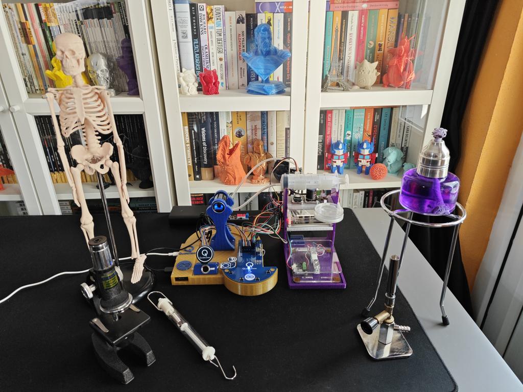
After mulling over different lab equipment options, I decided to construct my data set based on these items:
- Human skeleton model
- Microscope
- Alcohol burner
- Bunsen burner
- Dynamometer


I employed my phone's camera to capture lab equipment image samples, even though I implemented a sample collection option to the web dashboard later.


Step 4: Building an object detection model (FOMO) w/ Edge Impulse Enterprise
Since Edge Impulse provides developer-friendly tools for advanced AI applications and supports almost every development board through its vast model deployment options, I decided to utilize Edge Impulse Enterprise to build my object detection model. Also, Edge Impulse Enterprise incorporates elaborate model architectures for advanced computer vision applications and optimizes the state-of-the-art vision models for edge devices and single-board computers such as Arduino UNO Q.
Among the diverse machine learning algorithms provided by Edge Impulse, I decided to employ FOMO (Faster Objects, More Objects) since it is a groundbreaking algorithm optimized for both highly constrained edge devices and powerful single-board computers.
While labeling the lab equipment image samples, I simply applied the name of the target lab equipment:
- skeleton_model
- microscope
- alcohol_burner
- bunsen_burner
- dynamometer
Plausibly, Edge Impulse Enterprise enables developers with advanced tools to build, optimize, and deploy each available machine learning algorithm as supported firmware for nearly any device you can think of. Furthermore, since Qualcomm has recently purchased Arduino and Edge Impulse, there is an official pipeline to directly import Edge Impulse models into the Arduino App Lab by assigning your Arduino account to Edge Impulse Studio.
To utilize the advanced AI tools provided by Edge Impulse, you can register here.
For further information, you can inspect this FOMO object detection model on Edge Impulse as a public project.
Step 4.1: Uploading and labeling the lab equipment image samples
#️⃣ First, I created a new project on my Edge Impulse Enterprise account.

#️⃣ To employ the bounding box labeling tool for object detection models, I navigated to Dashboard ➡ Project info ➡ Labeling method and selected Bounding boxes (object detection).

#️⃣ To upload training and testing lab equipment image samples as individual files, I opened the Data acquisition section and clicked the Upload data icon.


#️⃣ Then, I navigated to Data acquisition ➡ Labeling queue to access all unlabeled items (training and testing) remaining in the provided image data set.
#️⃣ After drawing bounding boxes around target objects, I clicked the Save labels button to complete labeling an image sample. Then, I repeated this process until all lab equipment image samples retained at least one labeled target object.


Step 4.2: Training the FOMO object detection model
An impulse (an application developed and optimized by Edge Impulse) takes raw data, applies signal processing to extract features, and then utilizes a learning block to classify new data.
For my application, I created the impulse by employing the Image processing block and the Object Detection (Images) learning block.
Image processing block processes the passed raw image input as grayscale or RGB (optional) to produce a reliable features array.
Object Detection (Images) learning block represents the officially supported machine learning algorithms performing object detection.
#️⃣ First, I opened the Impulse design ➡ Create impulse section, set the model image resolution to 320 x 320, and selected the Fit shortest axis resize mode so as to scale (resize) the given image samples precisely. To complete the impulse creation, I clicked Save Impulse.

#️⃣ To modify the raw image features in the applicable format, I navigated to the Impulse design ➡ Image section, set the Color depth parameter as RGB, and clicked Save parameters.

#️⃣ Then, I proceeded to click Generate features to extract the required features for training by applying the Image processing block.


#️⃣ After extracting features successfully, I navigated to the Impulse design ➡ Object detection section and modified the neural network settings and architecture to achieve reliable accuracy and validity.
#️⃣ According to my prolonged experiments, I assigned the final model configurations as follows.
📌 Neural network settings:
- Number of training cycles ➡ 100
- Learning rate ➡ 0.001
- Validation set size ➡ 5%
📌 Neural network architecture:
- FOMO (Faster Objects, More Objects) MobileNetV2 0.35
#️⃣ After training the model with the final configurations, Edge Impulse evaluated the F1 score (accuracy) as 60.0% since I provided a very limited validation set, which does not even include samples for some labels.


Step 4.3: Evaluating the model accuracy and deploying the validated model
#️⃣ First, to obtain the validation score of the trained model based on the provided testing samples, I navigated to the Impulse design ➡ Model testing section and clicked Classify all.
#️⃣ Based on the initial F1 score, I started to rigorously experiment with the confidence score threshold value to pinpoint the optimum range for the real-world conditions.
#️⃣ After experimenting with the Unoptimized (float32) and Quantized (int8) model variants, I obtained the model accuracy (F1 score - precision) up to 70.0% and estimated the sweet spot for the threshold range.


#️⃣ To deploy the validated model optimized for my hardware, I navigated to the Impulse design ➡ Deployment section and searched for UNO Q.
#️⃣ I chose the Quantized (int8) model variant (optimization) to achieve the optimal performance while running the deployed model.
#️⃣ Finally, I clicked Build to deploy the model. However, contrary to the usual deployment procedure, I did not utilize the downloaded EIM binary since the Arduino App Lab provides a pipeline to link Edge Impulse accounts to import deployed models directly. Please refer to the following step to learn how to import deployed models via the provided Brick.


Step 5: Adding and adjusting the necessary Bricks to develop a feature-rich lab assistant application on the App Lab
As mentioned earlier, the Arduino App Lab provides pre-configured services and Docker containers, Bricks, to add various features to a custom App Lab application. Each Brick provides a specific set of capabilities that are executed by the Qualcomm MPU (Linux) and can be accessed by the Python script (backend) of the application via the built-in high-level APIs.
To develop my lab assistant App Lab application, I utilized these Bricks without using any additional third-party APIs or services:
#️⃣ To enable the Cloud LLM Brick to utilize Google Gemini, open its Brick configuration section and register the previously acquired Gemini API key.


#️⃣ To enable the Video Object Detection Brick to utilize my custom Edge Impulse FOMO object detection model, I employed the built-in pipeline to link my Arduino account with Edge Impulse Studio to import my FOMO model directly into the App Lab.
#️⃣ First, I signed in to my Arduino account on the Arduino App Lab.


#️⃣ Then, I opened the Video Object Detection Brick configuration section, clicked Train new AI model, and linked my Arduino account with Edge Impulse Studio to grant the App Lab access to my Edge Impulse account.


#️⃣ On Edge Impulse Studio, I selected the target development device for my project as Arduino UNO Q. Otherwise, the App Lab pipeline cannot access the essential model information to show importable models.


#️⃣ Then, on the App Lab, I installed my custom FOMO object detection model for identifying lab equipment.


#️⃣ After configuring Bricks, the App Lab updates the app.yaml file automatically to apply the requested changes.

Step 6: Programming the Python script (backend) executed by the Qualcomm QRB2210 microprocessor (MPU)
According to the App Lab application structure, this Python script behaves as the application backend and manages all data transfer processes, Brick features, and interconnected services.
📁 main.py
⭐ Include the required system and high-level Brick libraries.
import os
from arduino.app_bricks.video_objectdetection import VideoObjectDetection
from arduino.app_bricks.cloud_llm import CloudLLM, CloudModel
from arduino.app_bricks.web_ui import WebUI
from arduino.app_bricks.dbstorage_sqlstore import SQLStore
from arduino.app_utils import *
from datetime import datetime
from time import sleep
import re
import random
import string
import cv2
#️⃣ To bundle all the functions to write a more concise script, I used a Python class.
⭐ In the __init__ function:
⭐ Initialize the integrated Cloud LLM Brick to employ the provided Google Gemini API key to get access to gemini-2.5-flash. Also, assign the system prompt to ensure the LLM behaves as a lab assistant and generates AI lessons in the HTML format.
⭐ Initialize the built-in classifier instance of the Video Object Detection Brick, providing a real-time video stream over WebSocket, utilizing the installed Edge Impulse FOMO object detection model to precisely identify lab equipment. I adjusted confidence and debounce (intermission before executing the callback function for the same label) values based on my experiments on Edge Impulse Studio.
⭐ Declare the callback function to activate once the classifier detects lab equipment. In this case, using lambda is the most resource-efficient option to pass a variable to the given function.
⭐ Create a new SQL database via the Database Brick to register the user and LLM-produced lesson information. Then, create the essential database tables. The built-in table creation function checks whether the given table exists to avoid data loss. However, if requested, drop the previously generated tables to start with a clean slate.
⭐ Initiate the built-in WebUI Brick and declare the web dashboard's root folder path, which handles hosting the custom lab assistant web dashboard.
⭐ As the WebUI Brick establishes a WebSocket automatically, it allows the Python script to listen to WebSocket messages from the client (web dashboard) as the server and call assigned functions accordingly to process the transferred message (dictionary).
⭐ Via the WebUI Brick, expose an HTTP GET REST API endpoint to transfer the user account activation status and its associated LLM-generated lesson information to all clients, including the web dashboard. The Brick achieves this by executing the assigned Python function every time the exposed endpoint is called.
⭐ Employ the Arduino Router background Linux service to enable the STM32 MCU to borrow and run the provided functions on the Qualcomm MPU.
    def __init__(self, clean_tables=False):
        # Initialize the integrated Cloud LLM management module to utilize the provided Google (Gemini) API key to generate AI-based lab lessons.
        self.llm_gemini = CloudLLM(
            model=CloudModel.GOOGLE_GEMINI,
            system_prompt="You are a lab assistant and must generate HTML pages about the given questions by providing extensive information on the requested subject."
        )
        # Initialize the integrated object detection model classifier instance with video stream (over WebSocket) for the provided Edge Impulse FOMO object detection model to precisely identify lab equipment.
        self.edge_impulse_model = VideoObjectDetection(confidence=0.35, debounce_sec=5)
        # Define the callback function once the provided model detects an equipment.
        self.edge_impulse_model.on_detect_all(lambda detections: self.process_inference_results(detections))
        # Declare and create the SQL database to register user and lesson information.
        self.db = SQLStore("lab_assistant.db")
        # Create the essential database tables. The built-in table creation function checks whether the given table is already exists.
        if(clean_tables):
            self.db.drop_table("account_info")
            self.db.drop_table("lesson_info")
        self.db.create_table("account_info", {"user_id": "INT", "firstname": "TEXT", "lastname": "TEXT", "activation": "TEXT"})
        self.db.create_table("lesson_info", {"question": "TEXT", "equipment": "TEXT", "date": "TEXT", "user_id": "INT", "lesson_id": "TEXT", "filename": "TEXT"})
        # Declare the integrated WebUI Brick class instance to initiate the custom lab assistant web dashboard.
        self.web_ui = WebUI(assets_dir_path="/app/lab_web_dashboard")
        # Listen WebSocket messages from the client (web dashboard) to obtain the latest updates.
        self.web_ui.on_message("interface_web_control", self.interface_web_control_on_app)
        self.web_ui.on_message("manage_account_actions", self.manage_account_actions_on_app)
        self.web_ui.on_message("save_new_image_sample", self.save_new_image_sample_on_app)
        # Expose REST API endpoints (HTTP GET or POST) to transfer current user account and its associated AI-generated lesson information to all clients, including the web dashboard.
        self.web_ui.expose_api("GET", "/account_lessons", self.update_web_dashboard_with_database_info)
        # Declare the sensor variables array.
        self.sensor_values = {
                                 "pressure": 0,
                                 "alcohol_concentration": 0,
                                 "weight": 0,
                                 "no2": {"concentration": 0, "board_temp": 0},
                                 "geiger": {"cpm": 0, "nsvh": 0, "usvh": 0},
                                 "gnss": {"date": "", "utc": "", "lat_dir": "", "lon_dir": "", "latitude": 0, "longitude": 0, "altitude": 0, "sog": 0, "cog": 0}
                             }
        # Declare the essential account information holders.
        self.sign_up_account_info = None

        # Employ the Arduino Router background Linux service to enable STM32 MCU to borrow and run these functions on Qualcomm MPU.
        Bridge.provide("update_sensor_on_app", self.update_sensor_on_app)
        Bridge.provide("manage_account_actions_on_stm32", self.manage_account_actions_on_stm32)
⭐ In the process_inference_results function:
⭐ Once the built-in Brick classifier runs an inference with the provided Edge Impulse FOMO object detection model, process the retrieved results to obtain the detected label for the lab equipment.
⭐ Since the classifier returns a dictionary and sorts the detection results by confidence levels (scores), get the first dictionary item as the most accurate detection result.
⭐ If the user account is activated, transfer the processed detection result to the web dashboard via the established WebSocket.
    def process_inference_results(self, detections: dict):
        # According to my experiments, I noticed that the built-in detection function sorts the detection results while returning them as a dictionary based on confidence levels. Thus, I was able to get the first dictionary item to transfer the most accurate result once multiple items detected.
        label, result = next(iter(detections.items()))
        confidence = round(result[0]["confidence"], 2)
        # If the current user account is activated, transfer the processed detection result to the web dashboard.
        current_user = self.db.execute_sql("SELECT * FROM account_info WHERE activation = 'activated';")
        if(current_user != None):
            self.web_ui.send_message("latest_obj_detection_result", {"label": label, "confidence": confidence})
⭐ In the generate_AI_lesson_w_gemini function:
⭐ By utilizing the built-in Cloud LLM chat pipeline, ask the gemini-2.5-flash LLM to generate a lesson about the provided question in the HTML format.
⭐ Then, derive only the generated HTML page from the retrieved LLM response.
⭐ After obtaining the LLM-generated HTML page successfully, produce the unique 5-digit lesson ID. Then, save the HTML page by adding the account (user) ID, subject (equipment) name, and unique lesson ID to the file name.
#️⃣ Such as: 2_dynamometer_MJue4.html
⭐ Finally, insert the LLM-generated lesson information into the associated database table (SQL) and inform the web dashboard accordingly.
    def generate_AI_lesson_w_gemini(self, lesson_info):
        retrieved_llm_response = self.llm_gemini.chat("Generate an HTML page on this question: " + lesson_info["question"])
        # Derive only the generated HTML page from the retrieved LLM response.
        processed_llm_response = re.search(r'(<!DOCTYPE html>.*?</html>)', retrieved_llm_response, re.DOTALL)
        if(processed_llm_response):
            # If the provided LLM produces the lesson as an HTML page successfully:
            generated_lesson_html = processed_llm_response.group(1)
            # Generate the unique 5-digit lesson ID.
            unique_lesson_id = ''.join(random.choices(string.ascii_letters + string.digits, k=5))
            # Get the lesson generation date in the required format.
            date = datetime.now().strftime("%m %d, %Y %H:%M:%S")
            # Save the LLM-generated lesson as an HTML file.
            lesson_filename = str(lesson_info["user_id"]) + "_" + lesson_info["equipment"] + "_" + unique_lesson_id + ".html"
            with open("lab_web_dashboard/lessons/"+lesson_filename, "w", encoding="utf-8") as new_lesson:
                new_lesson.write(generated_lesson_html)
            # Register the generated lesson information to the associated database table.
            self.db.execute_sql("INSERT INTO lesson_info (`question`, `equipment`, `date`, `user_id`, `lesson_id`, `filename`) VALUES ('"+lesson_info["question"]+"', '"+lesson_info["equipment"]+"', '"+date+"', "+lesson_info["user_id"]+", '"+unique_lesson_id+"', '"+lesson_filename+"');")
            # Notify the web dashboard accordingly.
            self.web_ui.send_message("generate_ai_lesson_action", {"response": "Google (Gemini) [gemini-2.5-flash] produced the requested lesson successfully!"})
        else:
            self.web_ui.send_message("generate_ai_lesson_action", {"response": "🪐 Google (Gemini) [gemini-2.5-flash] LLM could not generate an appropriately-formatted HTML page. Please try again!"})
⭐ In the update_sensor_on_app function:
⭐ This function is provided to the Router (Bridge) service.
⭐ Once the STM32 MCU executes this function to transfer the collected sensor variables, round the variables to prevent overflow, save them to their respective dictionary items, and finally send the processed dictionary (sensor variables) to the web dashboard via WebSocket.
    def update_sensor_on_app(self, p, a, w, n_c, n_b, g_c, g_n, g_u, gn_d, gn_u, gn_lt_d, gn_ln_d, gn_lat, gn_lon, gn_alt, gn_sog, gn_cog):
        # Record the retrieved sensor variables to the associated array.
        self.sensor_values["pressure"] = round(p, 2)
        self.sensor_values["alcohol_concentration"] = round(a, 2)
        self.sensor_values["weight"] = round(w, 2)
        self.sensor_values["no2"]["concentration"] = round(n_c, 2); self.sensor_values["no2"]["board_temp"] = n_b
        self.sensor_values["geiger"]["cpm"] = g_c; self.sensor_values["geiger"]["nsvh"] = g_n; self.sensor_values["geiger"]["usvh"] = g_u
        self.sensor_values["gnss"]["date"] = gn_d; self.sensor_values["gnss"]["utc"] = gn_u; self.sensor_values["gnss"]["lat_dir"] = gn_lt_d; self.sensor_values["gnss"]["lon_dir"] = gn_ln_d; self.sensor_values["gnss"]["latitude"] = round(gn_lat, 4); self.sensor_values["gnss"]["longitude"] = round(gn_lon, 4); self.sensor_values["gnss"]["altitude"] = gn_alt; self.sensor_values["gnss"]["sog"] = gn_sog; self.sensor_values["gnss"]["cog"] = gn_cog
        # Transfer the obtained sensor information to the lab assistant web dashboard via the WebSocket connection.
        self.web_ui.send_message("sensor_values", self.sensor_values)
#️⃣ To maintain account generation and verification processes by employing the capacitive fingerprint sensor, I needed to chain operations executed by the Python backend and the STM32 MCU sequentially. To reduce the stress on the Bridge service, I utilized two functions to handle fingerprint authentication actions.
⭐ In the manage_account_actions_on_app function:
⭐ This function is called once the web dashboard requests via WebSocket.
⭐ Initiate the requested fingerprint task (register or verify) on the STM32 microcontroller via the borrowed interface_web_control function.
⭐ Once requested, log out the activated user account by updating the associated SQL database table.
⭐ Once requested, remove the activated user account and the LLM-generated lessons associated with the account by deleting the respective information from the associated SQL database tables.
⭐ Once requested, produce a new AI lesson about the provided question via Google Gemini (gemini-2.5-flash).
    def manage_account_actions_on_app(self, sid, data):
        com = data["command"]
        if(com == "signin_user"):
            # Initiate the associated fingerprint sensor task on the STM32 microcontroller via the borrowed function.
            Bridge.call("interface_web_control", "verify_id", int(data["given_user_id"]))
            sleep(1)
        elif(com == "signup_user"):
            self.sign_up_account_info = data;
            # Initiate the associated fingerprint sensor task on the STM32 microcontroller via the borrowed function.
            Bridge.call("interface_web_control", "register_id", -2)
            sleep(1)
        elif(com == "logout_user"):
            self.db.execute_sql("UPDATE account_info SET activation = 'not_activated' WHERE user_id = "+data["current_user_id"]+";")
        elif(com == "delete_user"):
            self.db.execute_sql("DELETE FROM account_info WHERE user_id = "+data["current_user_id"]+";")
            # Also delete all AI-generated lessons associated to this account.
            self.db.execute_sql("DELETE FROM lesson_info WHERE user_id = "+data["current_user_id"]+";")
        elif(com == "generate_new_ai_lesson"):
            self.generate_AI_lesson_w_gemini(data)
⭐ In the manage_account_actions_on_stm32 function:
⭐ This function is provided to the Router (Bridge) service.
⭐ Once the STM32 MCU sends the newly registered fingerprint ID, create a new user account with the previously received user information from the web dashboard. The transferred fingerprint ID is saved as the unique user ID to the associated SQL database table.
⭐ Once the STM32 MCU sends the verified (matched) fingerprint ID, activate the requested account if the verified user ID does not belong to a previously discarded account.
⭐ Inform the web dashboard of ongoing operations via WebSocket.
    def manage_account_actions_on_stm32(self, command, provided_user_id):
        if(command == "signup"):
            if(self.sign_up_account_info == None):
                self.web_ui.send_message("signup_action", {"response": "❌ Python backend did not receive the given user information!"})
            else:
                if(provided_user_id == -1):
                    self.web_ui.send_message("signup_action", {"response": "❌ Fingerprint sensor cannot register!"})
                elif(provided_user_id == -2):
                    self.web_ui.send_message("signup_action", {"response": "🔍 Fingerprint sensor cannot find an available ID!"})
                else:
                    # Create a new user account with the provided user information and the given fingerprint scan ID as the user ID.
                    self.db.execute_sql("INSERT INTO account_info (`user_id`, `firstname`, `lastname`, `activation`) VALUES ("+str(provided_user_id)+", '"+self.sign_up_account_info["firstname"]+"', '"+self.sign_up_account_info["lastname"]+"', 'activated');")
                    self.sign_up_account_info = None
                    self.web_ui.send_message("signup_action", {"response": "New user account successfully created!"})
        elif(command == "signin"):
            if(provided_user_id == -1):
                self.web_ui.send_message("signin_action", {"response": "🔍 The given user ID was not verified by the fingerprint sensor! Try again!"})
            elif(provided_user_id == -2):
                self.web_ui.send_message("signin_action", {"response": "❌ Fingerprint sensor cannot capture fingerprints precisely!"})
            else:
                # Activate the requested account via its verified (matched) user (fingerprint) ID.
                account_check = self.db.execute_sql("SELECT * FROM account_info WHERE user_id = "+str(provided_user_id)+";")
                if(account_check != None):
                    self.db.execute_sql("UPDATE account_info SET activation = 'activated' WHERE user_id = "+str(provided_user_id)+";")
                    self.web_ui.send_message("signin_action", {"response": "Account activated successfully!"})
                else:
                    self.web_ui.send_message("signin_action", {"response": "✍ Given fingerprint belongs to a previously removed account! Please register a new account!"})
⭐ In the update_web_dashboard_with_database_info function:
⭐ Since this function runs once the associated exposed REST API endpoint is called, it serves to dynamically update the web dashboard via the Python backend.
⭐ According to the account activation status and the number of LLM-generated lessons, produce HTML elements.
⭐ If there are LLM-generated lessons associated with the activated account, sort the retrieved lessons array based on their creation dates to produce an ordered list from latest to earliest. Then, based on the sorted lesson array, proceed to generate HTML lesson information cards.
⭐ Finally, depending on the account activation status, return the retrieved account information and generated HTML content.
    def update_web_dashboard_with_database_info(self):
        current_user = self.db.execute_sql("SELECT * FROM account_info WHERE activation = 'activated';")
        if(current_user == None):
            html_content = ('<article class="account_notification">'
                            '<h1><span>Sign In: </span>Please utilize the fingerprint sensor to activate your user account!</h1>'
                            '<div>'
                            '<section> <span>User ID</span> <input name="user_id" placeholder="1"></input> </section>'
                            '<section> <span>UNO Q</span> <span id="sign_in_button" class="highlight">Sign In</span> </section>'
                            '</div>'
                            '</article>'
                            '<article class="account_notification">'
                            '<h1><span>Sign Up: </span>Please enter your credentials and register your fingerprint to create a new account!</h1>'
                            '<div>'
                            '<section> <span>Firstname</span> <input name="firstname" placeholder="Kutluhan"></input> </section>'
                            '<section> <span>Lastname</span> <input name="lastname" placeholder="Aktar"></input> </section>'
                            '<section> <span>UNO Q</span> <span id="sign_up_button" class="highlight">Sign Up</span> </section>'
                            '</div>'
                            '</article>'
                           )
            return {"activation": "not_activated", "html_content": html_content}
        else:
            current_user = current_user[0]
            current_user_lessons = self.db.execute_sql("SELECT * FROM lesson_info WHERE user_id = "+str(current_user["user_id"])+";")
            html_content = ('<article class="account_notification" name="logout_section" user_id="'+str(current_user["user_id"])+'">'
                            '<h1><span>Hi, '+current_user["firstname"]+' '+current_user["lastname"]+' 😊</span> ID: ['+str(current_user["user_id"])+']</h1>'
                            '<div>'
                            '<section> <span>UNO Q</span> <span id="logout_button" class="highlight">Logout</span> </section>'
                            '<section> <span>UNO Q</span> <span id="delete_user_button" class="highlight">Delete Account</span> </section>'
                            '</div>'
                            '</article>'
                            )
            if(current_user_lessons != None):
                # Sort the retrieved lessons array based on their creation dates to produce an ordered list from latest to earliest.
                current_user_lessons.sort(key=lambda l: datetime.strptime(l["date"], "%m %d, %Y %H:%M:%S"), reverse=True)
                # Then, proceed generating HTML lesson information cards.
                for index, lesson in enumerate(current_user_lessons):
                    if(index==0): html_content += "<h2>Latest Lesson</h2>"
                    if(index==1): html_content += "<h2>Previous Lessons</h2>"
                    html_lesson = ('<article lesson_filename="lessons/'+lesson["filename"]+'">'
                                   '<h1><span>Q: </span>'+lesson["question"]+'</h1>'
                                   '<div>'
                                   '<section> <span>Date</span> <span>'+lesson["date"]+'</span> </section>'
                                   '<section> <span>User ID</span> <span>'+str(lesson["user_id"])+'</span> </section>'
                                   '<section> <span>Lesson ID</span> <span>'+lesson["lesson_id"]+'</span> </section>'
                                   '<section> <span>Subject</span> <span class="highlight">'+lesson["equipment"].upper()+'</span> </section>'
                                   '</div>'
                                   '</article>'
                                  )
                    html_content += html_lesson
            else:
                html_content += "<h2>No lesson found!</h2>"
            return {"activation": "activated", "firstname": current_user["firstname"], "lastname": current_user["lastname"], "user_id": current_user["user_id"], "html_content": html_content}
⭐ In the save_new_image_sample_on_app function:
⭐ This function is called once the web dashboard requests via WebSocket.
⭐ Stop the built-in model classifier running inferences with the provided FOMO model to release camera resources.
⭐ Then, via OpenCV, save the latest frame generated by the USB camera as a new lab equipment image sample by adding the requested label and the creation date to the file name.
⭐ Notify the web dashboard of ongoing operations via WebSocket.
⭐ Finally, release the OpenCV camera resources to resume the model classifier.
⚠️ As a gimmick, I programmed this function to allow users to capture new samples via the web dashboard. However, there is a caveat when restarting the model classifier: the real-time camera feed and inference results generated by the Video Object Detection Brick freeze, at least in App Lab 0.6.0.
    def save_new_image_sample_on_app(self, sid, data):
        # Stop the Edge Impulse classifier instance to release camera resources.
        self.edge_impulse_model.stop()
        sleep(1)
        # Save the latest generated frame (image) by the USB camera.
        usb_camera_feed = cv2.VideoCapture(0)
        success, latest_frame = usb_camera_feed.read()
        if(success):
            # Get the sample generation date.
            date = datetime.now().strftime("%Y%m%d_%H%M%S")
            sample_file_name = data["sample_label"] + "_" + date + ".jpg"
            cv2.imwrite("ei_model/new_samples/" + sample_file_name, latest_frame)
            # Notify the web dashboard accordingly.
            self.web_ui.send_message("save_sample_result", {"response": "🖼️ New image sample successfully saved! \n\n" + sample_file_name})
        else:
            # Notify the web dashboard accordingly.
            self.web_ui.send_message("save_sample_result", {"response": "❌ Cannot obtain the latest frame produced by the USB camera!"})
        # Release OpenCV camera resources before restarting the classifier instance.
        usb_camera_feed.release()
        sleep(5)
        # Resume the Edge Impulse classifier instance.
        self.edge_impulse_model.start()
        sleep(5)
⭐ In the interface_web_control_on_app function:
⭐ This function is called once the web dashboard requests via WebSocket.
⭐ Execute the borrowed interface_web_control function with the provided variables on the STM32 microcontroller.
    def interface_web_control_on_app(self, sid, data):
        Bridge.call("interface_web_control", data["command"], data["interface_num"])
        sleep(1)
⭐ In the __debug function, once requested, print the retrieved sensor variables on the built-in App Lab Python console for debugging.
    def __debug(self, _debug):
        if(_debug):
            print("\n\n/////// Collected Sensor Information ///////\n\n")
            for(main_key, main_value) in self.sensor_values.items():
                if(isinstance(main_value, dict)):
                    for (key, value) in main_value.items():
                        print("{}[{}]: {}\n".format(main_key, key, value))
                else:
                    print("{}: {}\n".format(main_key, main_value))
            print("\n////////////////////////////////////////////////\n\n")
⭐ Declare the main_loop function as the primary backend loop for the lab assistant App Lab application.
    def main_loop(self):
        while True:
            # Set 'True' for debugging on the built-in terminal.
            self.__debug(False)
            sleep(10)
⭐ Define the ai_lab_assistant class object.
⭐ Initiate the lab assistant App Lab application (backend) with the implemented Bricks.
ai_lab_assistant_obj = ai_lab_assistant();

# Initiate the main Arduino App application loop with the provided function, including the added Bricks.
App.run(user_loop=ai_lab_assistant_obj.main_loop)


#️⃣ After debugging for a while, make sure to clear the built-in Python console. Otherwise, the App Lab slows down or completely freezes due to excess data since the App Lab runs the application as a Docker container and tries to transfer all console data before each execution.
#️⃣ To clear the App Lab console (Python, Serial, etc.) and log information via the built-in App Lab CLI, including the Docker container logs, run this command in the terminal.
arduino-app-cli system cleanup

Step 7: Developing a full-fledged lab assistant web dashboard hosted directly by the Arduino App Lab
As mentioned earlier, the built-in WebUI Brick handles hosting of the provided web user interface. Thus, I only needed to develop the lab assistant web dashboard in compliance with the integrated WebSocket and let the Arduino App Lab host the dashboard automatically.
Please refer to the project GitHub repository to inspect all of the lab assistant web dashboard code files.
📁 socket.io.min.js
#️⃣ This script includes the necessary functions to communicate with the Python backend via WebSocket.

📁 default_equipment_questions.json
#️⃣ This file includes the JSON object literal containing predefined (static) questions about lab equipment, distinguished by the FOMO model labels.

📁 index.js
⭐ Import the predefined (static) lab equipment questions as a JSON object literal.
import default_questions from './default_equipment_questions.json' with {type:'json'};
⭐ Initiate the built-in WebSocket instance to communicate with the application's Python backend.
const socket = io(`http://${window.location.host}`);
⭐ Since the Python backend updates the web dashboard dynamically, track the first appearance of sign-in and sign-up forms to avoid flickering issues.
let form_shown = false;
⭐ To obtain the real-time inference result images (frames with bounding boxes) generated by the built-in Edge Impulse classifier, declare the specific embed URL produced by the Video Object Detection Brick (Docker container).
const ei_web_runner_embed = `http://${window.location.hostname}:4912/embed`;
⭐ To acquire the HTML content generated dynamically by the Python backend, every 2 seconds, make an HTTP GET request to the exposed REST API endpoint.
⭐ Process the obtained information according to the account activation status.
⭐ Ensure the web dashboard shows accurate information in the case of the user refreshing after account activation.
setInterval(() => {
	// Obtain the required updates from the integrated SQL database.
	$.ajax({
		url: "account_lessons",
		type: "GET",
		success: (response) => {
				// Process the obtained information.
                let container_element = $('div.gemini_lessons > section[cat="lesson_panel"]');
          		if(response["activation"] == "not_activated" && form_shown == false){
                  container_element.html(response["html_content"]);
                  form_shown = true;
                }
                if(response["activation"] == "activated"){
                  container_element.html(response["html_content"]);
                  form_shown = false;
                  // In case the user refreshes the web dashboard after the account activation.
                  if(refreshed){ return_state("account_activated"); refreshed = false; }
                }
			}
		});
}, 2000);
⭐ Every 10 seconds after the latest produced inference result, notify the user that the FOMO object detection model did not generate a successive inference result.
setInterval(() => {
    if(most_recent_detection == true){
      $('div.gemini_lessons > section[cat="object_detection"] > h2 > span').text("⏳ ");
      most_recent_detection = false;
    }
}, 10000);
⭐ In the return_state function, declare web dashboard states according to the account activation status.
function return_state(state){
  if(state == "default"){
      $('div.gemini_lessons > section[cat="object_detection"] > h2').text("🚀 Please activate your account");
      $('div.gemini_lessons > section[cat="object_detection"] > section > iframe').attr("src", "lessons/gemini_animations/gemini_obj_detection_waiting.html");
	  if($('div.gemini_lessons > section[cat="object_detection"] > section').hasClass("camera_show")) $('div.gemini_lessons > section[cat="object_detection"] > section').removeClass("camera_show");
      $('div.gemini_lessons > section[cat="lesson"] > iframe').attr("src", "lessons/gemini_animations/gemini_lesson_show_idle.html");
      $('div.gemini_lessons > section[cat="object_detection"] > div > article').html("");
      $('div.gemini_lessons > section[cat="object_detection"] > div > article').attr("latest_detected_equipment", "None");
  }else if(state == "account_activated"){
      $('div.gemini_lessons > section[cat="object_detection"] > h2').text("📸 Detecting lab equipment...");
	  if(!$('div.gemini_lessons > section[cat="object_detection"] > section').hasClass("camera_show")) $('div.gemini_lessons > section[cat="object_detection"] > section').addClass("camera_show");
      $('div.gemini_lessons > section[cat="object_detection"] > section > iframe').attr("src", ei_web_runner_embed);
  }
}
⭐ Declare analog interface (screen) numbers for each lab sensor, corresponding to their HTML variable cards.
const sensor_interface_num = {
	"home": -1,
	"no2": {"concentration": 0, "board_temp": 1},
	"alcohol_concentration": 2,
	"weight": 3,
	"geiger": {"cpm": 4, "nsvh": 5, "usvh": 6},
	"pressure": 7,
	"water": {"on": 8, "off": 8},
	"gnss": {"date": 9, "utc": 10, "lat_dir": 11, "lon_dir": 12, "latitude": 11, "longitude": 12, "altitude": 13, "sog": 14, "cog": 15},
};
⭐ Once the user clicks a lab sensor variable card:
⭐ Update the design of the clicked card and its adjacent cards that belong to the same lab sensor.
⭐ Via WebSocket, inform the Python backend of the analog interface (screen) number of the clicked card.
⭐ In the case of the clicked card belonging to the water atomization sensor, send the associated interface number with special commands since the STM32 MCU changes the atomization sensor's state (ON or OFF) based on these commands.
⭐ Finally, display the respective Gemini-generated static lab sensor information page, including basic experiment tips.
$('div.sensor_interface > section[cat="data"] > article').on("click", function(event){
    // Sensor card design updates.
	let item = $(this);
	let sensor_name = item.attr("sensor");
	let specified_variable = item.attr("sp");
	let interface_num = -1;
	let all_sensor_cards = $('div.sensor_interface > section[cat="data"] > article');
	let associated_cards = $('div.sensor_interface > section[cat="data"] > article[sensor="'+sensor_name+'"]');
	all_sensor_cards.each((index, elem) => { if($(elem).hasClass("highlight")) $(elem).removeClass("highlight"); if($(elem).hasClass("active")) $(elem).removeClass("active"); });
	if(!item.hasClass("active")) item.addClass("active");
	if(specified_variable != "none"){
		interface_num = sensor_interface_num[sensor_name][specified_variable];
		associated_cards.each((index, elem) => {
			if(!$(elem).hasClass("highlight") && !$(elem).hasClass("active")) $(elem).addClass("highlight");
		});
	}else{
		interface_num = sensor_interface_num[sensor_name];
	}
	// Tranfer the requested command and the associated lab assistant sensor interface number.
	/* Since the communication with the water atomization sensor is a special case, requiring the user to control the sensor state, I added a different command to enable the user to change its current state via its sensor variable cards. */
	if(sensor_name != "water"){
		socket.emit("interface_web_control", {"command": "update_interface", "interface_num": interface_num});
	}else{
		if(specified_variable == "on") socket.emit("interface_web_control", {"command": "update_water_on", "interface_num": interface_num});
		else if(specified_variable == "off") socket.emit("interface_web_control", {"command": "update_water_off", "interface_num": interface_num});
	}
    // Bring the respective information page generated by Gemini.
    let info_page = "experiments/gemini_"+sensor_name+".html";
    let showing_page = $('div.sensor_interface > section[cat="exp"] > iframe').attr("src");
    if(info_page != showing_page) $('div.sensor_interface > section[cat="exp"] > iframe').attr("src", info_page);
});
⭐ Once the user provides the required information to sign in, communicate with the Python backend via WebSocket to initiate the account activation procedure via fingerprint identification.
$('div.gemini_lessons > section[cat="lesson_panel"]').on("click", "#sign_in_button", function(event){
    // Obtain the provided user ID to initiate the account activation procedure.
    let given_user_id = $('div.gemini_lessons > section[cat="lesson_panel"] input[name="user_id"]').val();
    if(given_user_id != ""){
      let overlay = $('div.main > div.notification_overlay');
      if(overlay.hasClass("idle")) overlay.removeClass("idle");
      overlay.children("iframe").attr("src", "lessons/gemini_animations/gemini_fingerprint_waiting.html");
      // Notify the Python backend accordingly.
      socket.emit("manage_account_actions", {"command": "signin_user", "given_user_id": given_user_id});
    }else{
      alert("📝 Please fill all required areas!");
    }
});
⭐ Once the user provides the required information to sign up, communicate with the Python backend via WebSocket to initiate the account creation procedure via fingerprint registration.
$('div.gemini_lessons > section[cat="lesson_panel"]').on("click", "#sign_up_button", function(event){
    // Obtain the provided user information to create a new account.
    let firstname = $('div.gemini_lessons > section[cat="lesson_panel"] input[name="firstname"]').val();
    let lastname = $('div.gemini_lessons > section[cat="lesson_panel"] input[name="lastname"]').val();
    if(firstname != "" && lastname != ""){
      let overlay = $('div.main > div.notification_overlay');
      if(overlay.hasClass("idle")) overlay.removeClass("idle");
      overlay.children("iframe").attr("src", "lessons/gemini_animations/gemini_fingerprint_waiting.html");
      // Notify the Python backend accordingly.
      socket.emit("manage_account_actions", {"command": "signup_user", "firstname": firstname, "lastname": lastname});
    }else{
      alert("📝 Please fill all required areas!");
    }
});
⭐ Once the user requests, communicate with the Python backend via WebSocket to log out.
$('div.gemini_lessons > section[cat="lesson_panel"]').on("click", "#logout_button", function(event){
    // Obtain the user ID of the currently activated account.
    let current_user_id = $('div.gemini_lessons > section[cat="lesson_panel"] article[name="logout_section"]').attr("user_id");
    return_state("default");
	socket.emit("manage_account_actions", {"command": "logout_user", "current_user_id": current_user_id});
    alert("👋 Successfully signed out!");
});
⭐ Once the user requests, communicate with the Python backend via WebSocket to delete the activated user account.
❗ Note: I programmed the Python backend to discard all account and associated lesson information from the respective SQL database tables. Nonetheless, after account deletion, I chose to leave the AI lessons (HTML files) produced by Google Gemini in order to enable the user to conduct further research, since this is a proof-of-concept project.
$('div.gemini_lessons > section[cat="lesson_panel"]').on("click", "#delete_user_button", function(event){
    // Obtain the user ID of the currently activated account.
    let current_user_id = $('div.gemini_lessons > section[cat="lesson_panel"] article[name="logout_section"]').attr("user_id");
    return_state("default");
	socket.emit("manage_account_actions", {"command": "delete_user", "current_user_id": current_user_id});
    alert("❌ Account information and the associated lesson entries are removed from the database! \n\n📌Nonetheless, the AI-generated lesson (HTML) files remain for further research!");
});
⭐ Acquire the selected default lab equipment question from the presented list or the specific lab equipment question entered by the user via the HTML textarea element.
$('div.gemini_lessons > section[cat="object_detection"] > div > textarea').on("input click", function(event){
	provided_lesson_question = $(this).val();
	$('div.gemini_lessons > section[cat="object_detection"] > div > article > p').removeClass("clicked");
});

$('div.gemini_lessons > section[cat="object_detection"] > div > article').on("click", "p", function(event){
	$('div.gemini_lessons > section[cat="object_detection"] > div > article > p').removeClass("clicked");
	$(this).addClass("clicked");
	provided_lesson_question = $(this).text();
});
⭐ Once the user requests to generate a new AI lesson:
⭐ Obtain the latest detected lab equipment label by the FOMO model.
⭐ Verify whether the user has selected a default question or entered a specific one regarding the detected lab equipment.
⭐ If so, communicate with the Python backend via WebSocket to initiate the LLM-based lesson generation procedure, which utilizes Google Gemini — gemini-2.5-flash.
⭐ Inform the user of the lesson generation process accordingly.
⭐ Then, clear any previously selected or entered lesson questions to ensure a smooth subsequent LLM-based lesson generation.
$('div.gemini_lessons > section[cat="object_detection"]').on("click", "#generate_ai_lesson", function(event){
    // Obtain the user ID of the currently activated account.
    let current_user_id = $('div.gemini_lessons > section[cat="lesson_panel"] article[name="logout_section"]').attr("user_id");
    // Obtain the latest detected lab equipment by the provided Edge Impulse object detection model.
    let latest_detected_equipment = $('div.gemini_lessons > section[cat="object_detection"] > div > article').attr("latest_detected_equipment")
	// Check whether the user provided a lesson question or not.
	if(provided_lesson_question == ""){
		alert("🖥️ Please select (default) or request (enter) a lesson question!");
	}else{
        // Proceed to the LLM-based lesson generation if the object detection model has already detected a lab equipment. Otherwise, inform the user accordingly.
        if(latest_detected_equipment == "None"){
            alert("📸 Please show a lab equipment to the assistant to initiate the LLM-based lesson generation process.");
        }else{
		    // Notify the Python backend accordingly.
            socket.emit("manage_account_actions", {"command": "generate_new_ai_lesson", "question": provided_lesson_question, "equipment": latest_detected_equipment, "user_id": current_user_id});
		    // Inform the user of the lesson generation process.
		    let overlay = $('div.main > div.notification_overlay');
		    if(overlay.hasClass("idle")) overlay.removeClass("idle");
		    overlay.children("iframe").attr("src", "lessons/gemini_animations/gemini_lesson_waiting_generation.html");
		    overlay.children("h2").text("🤖 [gemini-2.5-flash] generating a new lesson on: " + provided_lesson_question);
		    // Then, clear previously given lesson question choices for performing the subsequent AI-based lesson generation accurately.
		    $('div.gemini_lessons > section[cat="object_detection"] > div > textarea').val("");
		    $('div.gemini_lessons > section[cat="object_detection"] > div > article > p').removeClass("clicked");
		    provided_lesson_question = "";
        }
	}
});
⭐ Once the user clicks a dynamically generated HTML AI lesson information card, show the respective LLM-generated lesson (HTML page) on the web dashboard.
$('div.gemini_lessons > section[cat="lesson_panel"]').on("click", '> article:not(.account_notification)', function(event){
    let lesson_filename = $(this).attr("lesson_filename");
    $('div.gemini_lessons > section[cat="lesson"] > iframe').attr("src", lesson_filename);
});
⭐ To make the lab assistant web dashboard behave as a single-page application, manage dashboard section transitions by visibility and animation.
$("div.header > div.menu_control").on("click", function(event){
	let menu_but_overlay = $(this).children("section:nth-child(3)");
	if(!menu_but_overlay.hasClass("to_right") && !menu_but_overlay.hasClass("to_left")){
		menu_but_overlay.addClass("to_right");
	}else if(menu_but_overlay.hasClass("to_right") && !menu_but_overlay.hasClass("to_left")){
		menu_but_overlay.removeClass("to_right");
		menu_but_overlay.addClass("to_left");
	}else if(!menu_but_overlay.hasClass("to_right") && menu_but_overlay.hasClass("to_left")){
		menu_but_overlay.removeClass("to_left");
		menu_but_overlay.addClass("to_right");
	}
});

$("div.header > div.menu_control > section:nth-child(3)").on("animationend", function(event){
	let menu_but_right = $(this).parent().children("section:nth-child(2)");
	let menu_but_left = $(this).parent().children("section:nth-child(1)");
	const applied_anim = event.originalEvent.animationName;
	if(applied_anim == "move_header_right"){
		menu_but_right.children("h2").addClass("highlighted");
		menu_but_left.children("h2").removeClass("highlighted");
		// Update dashboard section visibility accordingly.
		$("div.main > div.sensor_interface").removeClass("showing");
		$("div.main > div.gemini_lessons").addClass("showing");
	}else if(applied_anim == "move_header_left"){
		menu_but_left.children("h2").addClass("highlighted");
		menu_but_right.children("h2").removeClass("highlighted");
		// Update dashboard section visibility accordingly.
		$("div.main > div.gemini_lessons").removeClass("showing");
		$("div.main > div.sensor_interface").addClass("showing");
	}
});
⭐ Enable the user to provide a label and communicate with the Python backend via WebSocket to save the latest frame generated by the USB camera as a new sample.
$('div.gemini_lessons > section[cat="object_detection"] > section > div > button').on("click", function(event){
    // Get the given label for the image sample.
    let sample_label = $('div.gemini_lessons > section[cat="object_detection"] > section > div > input').val();
    if(sample_label != ""){
      // Inform the backend accordingly.
      socket.emit("save_new_image_sample", {"sample_label": sample_label});
    }else{
      alert("⚠️ Please enter a label for the new image sample!");
    }
});
⭐ Once the user requests, employ the built-in text-to-speech (TTS) module of the browser to read the selected lab sensor information page. Since the lab sensor guides are HTML documents shown in the associated HTML iframe element, acquire the content of the selected guide's body as plain text (discarding HTML tags) via the built-in text jQuery method.
⭐ Assign an end operation function to the module to notify the user of the speech completion time.
⭐ Also, enable the user to eliminate the ongoing speech with a subsequent click.
$('div.sensor_interface > section[cat="exp"] > span').on("click", function(event){
	// Get the contents of the target iframe as plain text.
	let lab_exp_container = $('div.sensor_interface > section[cat="exp"] > iframe');
	let lab_exp_src = lab_exp_container.attr("src");
	let lab_experiment_content = lab_exp_container.contents().find('body').text();
	// Check whether the user selected an example lab experiment.
	if(lab_exp_src != "experiments/gemini_home.html"){
		// Check if the text-to-speech module has already been activated to stop the ongoing speech with a subsequent click.
		if(window.speechSynthesis.speaking){
			// Halt the ongoing speech.
			if($(this).hasClass("initiated")) $(this).removeClass("initiated");
			window.speechSynthesis.cancel();
		}else{
			// Define custom module configurations.
			window.speechSynthesis.cancel();
			if(!$(this).hasClass("initiated")) $(this).addClass("initiated");
			const tts_module = new SpeechSynthesisUtterance(lab_experiment_content);
			tts_module.voice = googleVoices.find(v => v.name === "Google UK English Female");
			// Assign an end operation function to notify the user accordingly when the speech completed.
			tts_module.onend = function(event){
				if($('div.sensor_interface > section[cat="exp"] > span').hasClass("initiated")) $('div.sensor_interface > section[cat="exp"] > span').removeClass("initiated");
			    const milliseconds = Math.floor(event.elapsedTime / 1000);
				const minutes = Math.floor(milliseconds / 60);
				const seconds = milliseconds % 60;
				const total_elapsed_time = `${minutes} minutes and ${seconds} seconds`;
				alert("📚 Selected lab experiment text-to-speech event completed in " + total_elapsed_time + ".");
			};
			// Initiate the integrated text-to-speech module.
			window.speechSynthesis.speak(tts_module);
		}
	}else{
		alert("🔊 Please select an example lab experiment to be able to utilize the built-in browser text-to-speech module!");
	}
});
⭐ Once the user requests, employ the built-in text-to-speech module of the browser to read the selected LLM-generated (Google Gemini) lesson. Since the AI lessons are HTML documents shown in the associated HTML iframe element, acquire the content of the selected lesson's body as plain text (discarding HTML tags) via the built-in text jQuery method.
⭐ Assign an end operation function to the module to notify the user of the speech completion time.
⭐ Also, enable the user to eliminate the ongoing speech with a subsequent click.
$('div.gemini_lessons > section[cat="lesson"] > span').on("click", function(event){
	// Get the contents of the target iframe as plain text.
	let lesson_container = $('div.gemini_lessons > section[cat="lesson"] > iframe');
	let lesson_src = lesson_container.attr("src");
	let lesson_content = lesson_container.contents().find('body').text().trim();
	// Check whether the user selected a previously generated lesson.
	if(lesson_src != "lessons/gemini_animations/gemini_lesson_show_idle.html"){
		// Check if the text-to-speech module has already been activated to stop the ongoing speech with a subsequent click.
		if(window.speechSynthesis.speaking){
			// Halt the ongoing speech.
			if($(this).hasClass("initiated")) $(this).removeClass("initiated");
			window.speechSynthesis.cancel();
		}else{
			// Define custom module configurations.
			window.speechSynthesis.cancel();
			if(!$(this).hasClass("initiated")) $(this).addClass("initiated");
			const tts_module_lesson = new SpeechSynthesisUtterance(lesson_content);
			// Assign an end operation function to notify the user accordingly when the speech completed.
			tts_module_lesson.onend = function(event){
				if($('div.gemini_lessons > section[cat="lesson"] > span').hasClass("initiated")) $('div.gemini_lessons > section[cat="lesson"] > span').removeClass("initiated");
			    const milliseconds = Math.floor(event.elapsedTime / 1000);
				const minutes = Math.floor(milliseconds / 60);
				const seconds = milliseconds % 60;
				const total_elapsed_time = `${minutes} minutes and ${seconds} seconds`;
				alert("📚 Selected lesson text-to-speech event completed in " + total_elapsed_time + ".");
			};
			// Initiate the integrated text-to-speech module.
			window.speechSynthesis.speak(tts_module_lesson);
		}
	}else{
		alert("🔊 Please select a previously generated lesson (Gemini) to be able to utilize the built-in browser text-to-speech module!");
	}
});
⭐ Subscribe to WebSocket messages transferred by the server (Python backend) to obtain and show the latest lab sensor readings, acquire and register the latest lab equipment detection results produced by the Edge Impulse FOMO object detection model, and process ongoing operation progress information to inform the user accordingly.
socket.on("sensor_values", (values) => {
// Process the received object (Python backend) to obtain and print the retrieved sensor variables.
Object.keys(values).forEach((main_key) => {
if(typeof(values[main_key]) === "object"){
Object.keys(values[main_key]).forEach((key) => {
$('div.sensor_interface > section[cat="data"] > article[sensor="'+main_key+'"][sp="'+key+'"] > h2').text(values[main_key][key]);
});
}else{
$('div.sensor_interface > section[cat="data"] > article[sensor="'+main_key+'"] > h2').text(values[main_key]);
}
});
});
socket.on("latest_obj_detection_result", (detection) => {
// Process the received object (Python backend) to obtain the latest lab equipment detection results generated by the provided Edge Impulse FOMO object detection model.
let detected_label = detection["label"];
let confidence = String(detection["confidence"]);
let default_questions_container = $('div.gemini_lessons > section[cat="object_detection"] > div > article');
default_questions_container.attr("latest_detected_equipment", detected_label);
let associated_default_questions = default_questions[detected_label];
let question_html_content = "";
associated_default_questions.forEach((question) => {
question_html_content += "<p>" + question + "</p>";
});
if(question_html_content != "") default_questions_container.html(question_html_content);
// Notify the user of the detected label and confidence level.
const label_logo = {"skeleton_model": "💀 ", "microscope": "🔬 ", "alcohol_burner": "⚗️ ", "bunsen_burner": "🪔 ", "dynamometer": "⏲️ "};
$('div.gemini_lessons > section[cat="object_detection"] > h2').html("<span>" + label_logo[detected_label] + "</span>" + detected_label + " [" + confidence + "]");
most_recent_detection = true;
});
socket.on("signup_action", (r) => {
// Process the responses from the Python backend while creating a new user account, distinguished by the registered fingerprint.
let response = r["response"];
let overlay = $('div.main > div.notification_overlay');
if(response != "New user account successfully created!"){
overlay.children("h2").text(response);
}else{
if(!overlay.hasClass("idle")) overlay.addClass("idle");
overlay.children("iframe").attr("src", "");
overlay.children("h2").text("Please scan your fingerprint!");
return_state("account_activated");
alert("🚀 " + response);
}
});
socket.on("signin_action", (r) => {
// Process the responses from the Python backend while handling the account activation procedure.
let response = r["response"];
let overlay = $('div.main > div.notification_overlay');
if(response != "Account activated successfully!"){
overlay.children("h2").text(response);
}else{
if(!overlay.hasClass("idle")) overlay.addClass("idle");
overlay.children("iframe").attr("src", "");
overlay.children("h2").text("Please scan your fingerprint!");
return_state("account_activated");
alert("🚀 " + response);
}
});
socket.on("generate_ai_lesson_action", (r) => {
// Process the responses from the Python backend while producing a new lesson via the provided Cloud LLM (Gemini).
let response = r["response"];
let overlay = $('div.main > div.notification_overlay');
if(response != "Google (Gemini) [gemini-2.5-flash] produced the requested lesson successfully!"){
overlay.children("h2").text(response);
}else{
if(!overlay.hasClass("idle")) overlay.addClass("idle");
overlay.children("iframe").attr("src", "");
overlay.children("h2").text("Please scan your fingerprint!");
alert("👩🚀 " + response);
}
});
socket.on("save_sample_result", (r) => {
// Process the responses from the Python backend on the new image sample generation process.
let response = r["response"];
alert(response);
});


📁 root_variables.css and index.css
#️⃣ These files include all CSS classes and configurations.
#️⃣ Please refer to the project GitHub repository to review the lab assistant web dashboard design (styling) files.


📁 index.html
#️⃣ This file represents the primary user interface and control panel provided by the lab assistant web dashboard and gets updated dynamically by the Python backend.
#️⃣ Please refer to the project GitHub repository to review.


📁 Gemini-assisted
#️⃣ As mentioned earlier, I employed the official Gemini chat application to produce static lab sensor guides with experiment tips and custom logos, whose file names have the gemini moniker.


Step 7.1: Ensuring the lab assistant App Lab application operates as anticipated to enable easy importing for further research cases
After completing the development of the lab assistant App Lab application, I rechecked all code files, assets, and configurations to make sure the application was ready for exporting without any errors.
📚 The finalized lab assistant App Lab application directory structure (alphabetically) is as follows:
Please refer to the project GitHub repository to review all files.
- /data
- /ei_model
- /new_samples
- ai-driven-ancillary-lab-assistant-w-uno-q-linux-aarch64-v1.eim
- /lab_web_dashboard
- /assets
- /img
- /script
- default_equipment_questions.json
- index.js
- socket.io.min.js
- /style
- index.css
- root_variables.css
- /experiments
- gemini_alcohol_concentration.html
- gemini_geiger.html
- gemini_gnss.html
- gemini_home.html
- gemini_no2.html
- gemini_pressure.html
- gemini_water.html
- gemini_weight.html
- /lessons
- /gemini_animations
- gemini_fingerprint_waiting.html
- gemini_lesson_show_idle.html
- gemini_lesson_waiting_generation.html
- gemini_obj_detection_waiting.html
- index.html
- /python
- main.py
- /sketch
- /customLibs
- /DFRobot_Geiger
- /DFRobot_ID809
- /DFRobot_MultiGasSensor
- /modded_Adafruit_GC9A01A_1.1.1
- /modded_DFRobot_Alcohol_1.0.0
- /modded_DFRobot_GNSS_1.0.0
- /modded_DFRobot_HX711_I2C_1.0.0
- color_theme.h
- logo.h
- sketch.ino
- sketch.yaml
- app.yaml
- README.md


#️⃣ I edited the app.yaml file via the GNU nano text editor to add a description and change the application icon (emoji). I also wrote a simple README file redirecting to the project tutorial.


After revising the app.yaml file, I exported my lab assistant App Lab application as a ZIP folder. Then, I imported the ZIP folder into the App Lab to see whether the application was ready for sharing publicly.
Please refer to the project GitHub repository to download the application's ZIP folder.
#️⃣ To import the lab assistant App Lab application, navigate to Create new app + ➡ Import App and select the downloaded ZIP folder.


#️⃣ Once you import the lab assistant App Lab application, it comes with the default configurations for the Video Object Detection Brick (yolox-object-detection) and Cloud LLM Brick (no API key).
#️⃣ Thus, as explained in previous steps, please make sure to link your Arduino account to Edge Impulse Studio to employ my publicly available Edge Impulse FOMO object detection model for identifying lab equipment and register your unique Google Gemini API key.


After importing the lab assistant App Lab application and reassigning the required Brick configurations, I meticulously tested all application features and did not encounter any issues.


Step 7.2: Timeout issues with the latest Zephyr platform release (0.54.1)
The lab assistant App Lab application was working flawlessly until the latest Zephyr Arduino core (arduino:zephyr) release (0.54.1). Once I updated Zephyr platform to this release on the Arduino App Lab, the application started to throw timeout errors incessantly and was not able to establish data transfer between the Qualcomm MPU and the STM32 MCU via the Arduino Router background Linux service. The application was not even able to run the sketch on the MCU since the Router (Bridge) service intercepted the code flow.
After putting a lot of effort into running the application, I came to the conclusion that installing the Arduino_RouterBridge library as a custom sketch library outside of the bundled Zephyr platform (Arduino UNO Q Board) takes up additional dynamic memory space as global variables.
Before the release of the 0.54.1 Zephyr Arduino core version, the bundled Zephyr platform included the Arduino_RouterBridge library to make it available to all App Lab applications. Nonetheless, it was removed in the 0.54.1 version and needs to be installed as a custom sketch library per application.
As I was programming the application sketch, I needed to deliberately optimize functions and the number of global variables to enable the STM32 MCU to utilize the Router service without timeout errors and incompatibilities.
Once I updated the Arduino App Lab to the 0.54.1 version, I installed the Arduino_RouterBridge library as requested and started to get continuous timeout errors regarding the Router service despite all my efforts to fix them.


As mentioned, in this case, I assume timeout errors occur because the installed Arduino_RouterBridge library requires more space from the already squeezed dynamic memory than the preconfigured (bundled) one.
Since I did not want to eliminate lab assistant features and could not optimize my sketch any further, I decided to revert the App Lab to the 0.53.1 Zephyr platform version via the Arduino CLI.
arduino-cli core uninstall arduino:zephyr
arduino-cli core install arduino:zephyr@0.53.1
arduino-cli burn-bootloader -b arduino:zephyr:unoq -P jlink
While using the 0.53.1 version, I did not encounter any timeout errors or incompatibilities again.


Step 7.3: Continuing issues with the most recent Zephyr platform (0.55.0)
After I completed this project tutorial and was nearing publication, Arduino released new updates for Arduino App Lab and the Zephyr Arduino core (arduino:zephyr). Thus, I decided to test these new versions to see whether the timeout issues remain.
#️⃣ Once you open the Arduino App Lab, it should ask permission to install the latest versions automatically.
- arduino:zephyr Version 0.55.0
- arduino-app-cli Version 0.9.0
- arduino-app-lab Version 0.7.0
- arduino-router Version 0.8.1
After installing the updates, I tested my lab assistant application and confirmed that the application runs without the timeout errors mentioned above. However, unfortunately, there are different problems regarding the Bridge library. The hardware serial (UART) port does not work properly and behaves as the built-in Monitor. Thus, the fingerprint sensor does not operate properly.


When I inspected the library source code to solve this issue, I noticed that Monitor and Serial became synonymous in this version. Thus, I tried to utilize Serial1 as the hardware port since the documentation shows that the port number increases automatically depending on the applied serial tasks, such as serial USB, Monitor, hardware, etc.
Although I managed to run the hardware serial port in this way, the sketch program started to malfunction, causing loops, initiating tasks randomly, and generating faulty sensor data.

Finally, again, I decided to revert the App Lab (0.7.0) to the 0.53.1 Zephyr platform version via the Arduino CLI. Then, everything started to work as expected without any issues.


Step 8: Designing the lab assistant analog interface PCB as an Arduino UNO Q shield (hat)
After developing the lab assistant App Lab application and ensuring all electronic components work as expected, I started to design the lab assistant analog interface PCB layout. According to my refined development process for modeling distinct PCBs and compatible 3D parts, I prefer designing PCB outlines and layouts (silkscreen, copper layers, etc.) directly on Autodesk Fusion 360 and culminating my proof-of-concept device structures around the PCB layouts. Having a PCB digital twin allows me to simulate a complex 3D mechanical structure to make its components compatible with the PCB's part placement and outline before sending the PCB design for manufacturing. In this case, creating the PCB layout on Fusion 360 was greatly beneficial since I decided to design the analog interface PCB as a unique Arduino UNO Q shield (hat).
As I was working on the analog interface PCB layout, I leveraged the open-source CAD file of Arduino UNO Q to obtain accurate measurements:
- ✒️ Arduino UNO Q (Step) | Inspect
#️⃣ First, I drew the PCB outline to make sure the UNO Q female pin headers align perfectly with the shield.
#️⃣ In the spirit of designing an authentic shield, I employed Google Gemini to generate a unique lab assistant robot icon. Then, I inscribed the Gemini-generated icon as a part of the PCB outline.
#️⃣ I also added two contrasting openings (holes) to the PCB as guiding features.
#️⃣ Finally, I thoroughly measured the areas of the electrical components with my caliper and placed them in the borders of the PCB outline diligently, including the male pin headers, which would be on the back of the PCB for attaching the shield onto the Arduino UNO Q.


After designing the PCB outline and structure, I imported my outline graphic into KiCad 9.0 in the DXF format and created the necessary circuit connections to complete the analog interface PCB layout.
As I had already tested all electrical components while programming the UNO Q, I was able to create the circuit schematic effortlessly in KiCad by following the prototype connections.

After completing the circuit schematic, I finalized the analog interface PCB layer connections and configurations.


Step 8.1: Soldering and assembling the lab assistant analog interface PCB
For further inspection, I provided the Gerber and fabrication files on the project GitHub repository.
❗ Important: As I was designing the circuitry, I forgot to add a dedicated header for the electrochemical NO2 sensor. Since I tested lots of lab sensors employing the I2C communication protocol while developing the lab assistant, I missed that the NO2 sensor did not have a dedicated header in the final layout. Thus, I utilized a mini breadboard to split the I2C line and connect the NO2 sensor. As long as you have an I2C-compatible sensor, you can connect it directly via the three dedicated I2C ports on the PCB. If you want to connect more than three I2C sensors, you can split the I2C line as I did.
#️⃣ After receiving my PCBs, I soldered electronic components and pin headers via my TS100 soldering iron to place all parts according to my PCB layout.
📌 Component assignments on the lab assistant analog interface PCB:
A1 (Headers for Arduino UNO Q)
Fingerprint_Sensor1 (Headers for Capacitive Fingerprint Sensor)
Geiger_Counter1 (Headers for Geiger Counter Module)
Alcohol_Sensor1 (Headers for Electrochemical Alcohol Sensor)
Water_Atomization1 (Headers for Water Atomization Sensor)
Weight_Sensor1 (Headers for Weight Sensor)
Pressure_Sensor1 (Headers for Integrated Pressure Sensor)
GNSS1 (Headers for GNSS Positioning Module)
Round_LCD1 (Headers for GC9A01 Round LCD Display)
K1, K2, K3, K4 (6x6 Pushbutton)
D1 (5mm Common Anode RGB LED)
R1, R2, R3 (220Ω Resistor)
J_3.3V_1 (DC Barrel Female Power Jack)
J_3.3V_2 (Headers for Power Supply)


#️⃣ I soldered the dedicated UNO Q male headers to the back of the analog interface PCB to attach it as a shield (hat) onto the Arduino UNO Q.

Step 9: Modeling the ancillary lab assistant 3D components to form the final device structure
In the spirit of building a feature-rich and laboratory-worthy AI-driven ancillary lab assistant structure, I decided to design a rigid assistant base and a modular lab sensor ladder from the ground up, including a dedicated USB camera stand.
As a frame of reference for those who aim to replicate or improve this ancillary lab assistant, I shared the design files (STL) of all 3D components as open-source on the project GitHub repository.
🎨 I sliced all the exported STL files in Bambu Studio and printed them using my Bambu Lab A1 Combo. In accordance with my color theme, I utilized these PLA filaments while printing 3D parts of the lab assistant:
- eSun e-Twinkling Gold
- eSun e-Twinkling Blue
- eSun e-Twinkling Purple
- eSun e-Twinkling Silver
The pictures below show the final version of the lab assistant structure on Fusion 360. I will thoroughly explain all of my design choices and the assembly process in the following steps.


Step 9.a: Designing the base of the ancillary lab assistant
#️⃣ First, I designed the lab assistant base, which embeds the Arduino UNO Q and the UGREEN 5-in-1 USB hub (dongle).
#️⃣ I added two pegs to easily place the analog interface PCB via its guiding features and ensured the PCB outline has enough clearance once attached onto the UNO Q as a shield.
#️⃣ To secure the USB dongle and its USB-C cable connected to the UNO Q, I designed a specific USB hub cover.
#️⃣ I designed the base to allow the user to access all USB hub ports (5-in-1), including HDMI, once the hub cover is installed.
#️⃣ To build an intuitive analog interface, I designed a unique round display and capacitive fingerprint sensor mount.
#️⃣ I also designed a unique USB camera stand compatible with the A4 Tech PK-910H USB webcam. I estimated the camera stand height by considering the camera FOV (Field of View) to avoid capturing the obstructing front base section.
#️⃣ All component connections, including the Arduino UNO Q, are established via self-tapping (secure fit) M2 holes.


Step 9.a.1: Printing and assembling the assistant base
#️⃣ I sliced the assistant base with 10% sparse infill density instead of the default 15%.
#️⃣ To highlight the brand logos on the USB hub cover, I applied the built-in Bambu Studio painting tool.
#️⃣ To strengthen the round display mount, I set its wall loop (perimeter) number to 3.


#️⃣ After printing the mentioned components, I did not need to install any reinforcer, such as heat (threaded) inserts, since I added self-tapping (secure fit) M2 holes for each mechanical connection.
#️⃣ First, I attached the Arduino UNO Q to the assistant base via M2 screws.


#️⃣ I connected the UGREEN USB dongle (hub) to the UNO Q and embedded it into the base via its dedicated slot and semi-circular cable groove.
#️⃣ Then, I attached the USB hub cover to the assistant base via M2 screws to secure the USB dongle. To prevent putting too much stress on the UNO Q USB-C connector, I utilized M2 hex nuts as spacers between the hub cover and the base.


#️⃣ Thanks to the front and left openings of the base, it is possible to access all USB hub ports, 5-in-1, after closing the USB hub cover. Before proceeding with the assembly, I tested the USB hub connectivity by connecting the USB camera (PK-910H) and my HDMI screen.


#️⃣ Since I specifically designed the camera stand to clearance-fit the PK-910H USB camera (webcam) without its factory mount clip, I removed its clip and inserted the USB camera directly into the USB camera stand.
#️⃣ I attached the camera stand and the round display mount to the assistant base via M2 screws.
#️⃣ I fastened the GC9A01 round display to the round display mount via M2 screws. Since the round display module has preinstalled M2 connection nuts, I designed the corresponding M2 holes on the display mount as clearance holes.
#️⃣ Finally, I passed the 6-pin FPC cable of the capacitive fingerprint sensor to position the sensor into its dedicated slot on the display mount.


Step 9.b: Designing the experiment-ready modular lab assistant sensor ladder
#️⃣ To allow users to conduct experiments with the implemented lab sensors and their associated tools intuitively, I designed this modular lab sensor ladder containing all of the lab sensors and secondary tools at its four levels.
#️⃣ Each horizontal row (rung) of the sensor ladder includes dedicated slots and snap-fit joints for specific lab sensors and their secondary tools, such as the syringe for the pressure sensor.
- 0️⃣Floor:
- Gravity: 1Kg Weight Sensor Kit - HX711
- 1️⃣ Rung (Row):
- Gravity: Geiger Counter Module - Ionizing Radiation Detector
- 2️⃣ Rung (Row):
- Gravity: Electrochemical Alcohol Sensor
- Gravity: Electrochemical Nitrogen Dioxide Sensor - NO2
- Grove - Water Atomization Sensor - Ultrasonic
- 60 mm Petri Dish
- 3️⃣ Rung (Row):
- Gravity: GNSS Positioning Module
- Grove - Integrated Pressure Sensor Kit - MPX5700AP
- Syringe with rubber tube
#️⃣ I added a slot for the 60 mm petri dish in order to provide water to the ultrasonic transducer of the water atomization sensor to run it effortlessly.
#️⃣ The syringe and its rubber tube are part of the pressure sensor kit and let the user gauge the applied pressure to the MPX5700AP sensor.


Step 9.b.1: Printing and assembling the lab assistant sensor ladder
#️⃣ To print the sensor ladder walls precisely, I utilized tree (slim) supports and enabled the support critical regions only option, which avoids unsolicited support placements.
#️⃣ Since the ladder rungs (rows) have notches that slide into the ladder walls, I needed to place supports very delicately to prevent extra friction or stuckness due to excess material. After some trial and error, I found that normal supports and the Snug support style with special settings work perfectly to print narrow grooves with the e-Twinkling filament type.
- Type ➡️ normal (auto)
- Style ➡️ Snug
- Top interface layers ➡️ 0
- Bottom interface layers ➡️ 0
- Support/object first layer gap ➡️ 0.3
- Don't support bridges ➡️ ✅


#️⃣ Although the ladder walls grip the ladder floor strongly enough through mortise and tenon joints, I still strengthen their connection via M2 screws and nuts through M2 clearance holes.


#️⃣ Then, I slid the ladder rungs toward the ladder wall pegs through their dedicated notches. Even though I added M2 clearance holes to reinforce the rung-wall connections, I did not need to use them, as the friction force was more than enough to secure them.


#️⃣ As I was placing the ladder rungs, I attached the associated sensors on their dedicated slots via M2 screws and nuts through M2 clearance holes. For sensors requiring lifting for cable connections, I utilized additional M2 nuts as spacers.


#️⃣ Finally, I placed the weight sensor kit onto the ladder floor and attached secondary sensor tools to their dedicated slots and snap-fit joints.


Step 9.c: Final adjustments and installing the analog interface PCB
#️⃣ After completing the lab assistant base and sensor ladder assembly, I attached the analog interface PCB to the Arduino UNO Q via the dedicated male pin headers. Thanks to the PCB's guiding features (holes) and the corresponding base pegs, it was effortless to align and secure the PCB.


#️⃣ Then, I connected all of the lab sensors to the analog interface PCB via their integrated Gravity-to-jumper and Grove-to-jumper cables. As mentioned earlier, I forgot to add a dedicated I2C port for the NO2 sensor. Thus, I utilized a mini breadboard to split the I2C line and connect the NO2 sensor.


#️⃣ I employed a hot glue gun to affix the capacitive fingerprint sensor and the active ceramic antenna (GPS/BeiDou) to their dedicated slots.


#️⃣ After completing all sensor connections, I utilized zip ties to establish proper cable management.

#️⃣ Finally, I meticulously tested all of the lab assistant features via the Arduino App Lab network mode to ensure the lab assistant is ready to publish and share as an open-source project.


#️⃣ Everything worked flawlessly except my external power source, which experienced inconsistent voltage drops while supplying all 3.3V lab sensors. Thus, I decided to connect the buck-boost converter directly to my phone charger instead of the power bank. After changing the external power supply, I did not encounter any power issues.

#️⃣ After finalizing the lab assistant structure and ensuring that all lab assistant features and components operate as intended, I started to prepare this project tutorial.


Outcomes: Conducting LLM-assisted lab experiments with the integrated lab sensors
🤖🔬🧬🧫 Once the user initiates the ancillary lab assistant, the assistant activates the home (default) state on the analog interface and waits for user inputs.
🤖🔬🧬🧫 After initiating a different analog interface state, the assistant lets the user return to the home (default) state by pressing the control button D.

🤖🔬🧬🧫 The analog lab assistant interface allows the user to manually change the analog interface state to monitor dedicated lab sensor data screens by sensor name and variable type.
- Control button A ➡ Next (+)
- Control button B ➡ Previous (-)

🤖🔬🧬🧫 If there are any communication protocol errors, the lab assistant informs the user immediately on the round GC9A01 screen.


🤖🔬🧬🧫 On the Sensor Experiments section of the lab assistant web dashboard, the user can inspect real-time variables (readings) produced by the lab sensors, presented as lab sensor information cards distinguished by sensor names and variable types.


❗ I did not notice that the alcohol concentration was a lot higher than expected while capturing these screenshots. Once I noticed, I checked and saw that I had forgotten the alcohol burner lid open near the sensor for a while :)


🤖🔬🧬🧫 The web dashboard lets the user select a lab sensor information card to display the selected sensor's Gemini-generated (static) information page, including a simple sensor guide and related laboratory experiment tips.
🤖🔬🧬🧫 Then, the analog assistant interface shows the dedicated lab sensor data screen on the round display.
📡 Pressure (Integrated)
📡 Alcohol (Concentration)


📡 Weight (Estimation)


📡 Water (Atomization)
#️⃣ The water atomization sensor cards are special since they control the sensor state (ON or OFF) instead of showing readings. I will thoroughly explain how they operate below.


📡 NO2 (Concentration)


📡 NO2 (Board Temperature)


📡 Geiger (CPM)


📡 Geiger (nSv/h)


📡 Geiger (μSv/h)


📡 GNSS (Date)


📡 GNSS (UTC)


📡 GNSS (Latitude Direction)


📡 GNSS (Longitude Direction)


📡 GNSS (Latitude)


📡 GNSS (Longitude)


📡 GNSS (Altitude)


📡 GNSS (Speed Over Ground)


📡 GNSS (Course Over Ground)


🤖🔬🧬🧫 The web dashboard enables the user to employ the integrated TTS (text-to-speech) module of the browser to listen to the Gemini-generated (static) lab sensor information pages by clicking the dedicated speech button on the top left corner of the information page iframe.
🤖🔬🧬🧫 Via a subsequent click on the speech button, the web dashboard stops the ongoing speech immediately.


🤖🔬🧬🧫 Once the TTS module finishes reading the selected sensor information page, the web dashboard informs the user of the speech completion time.


🤖🔬🧬🧫 If there is no selected information card once the speech button is clicked, the web dashboard informs the user accordingly.

🤖🔬🧬🧫 Once the user selects the Home Interface card, the web dashboard brings the default experiment animation, and the analog interface returns to the home (default) state.


🤖🔬🧬🧫 Based on each lab sensor's specifications and capabilities, which can be inspected via the LLM-generated guides, I came up with simple yet insightful experiments. As mentioned earlier, even though I employed Google Gemini to generate lab sensor information pages, I utilized its official chat application to produce static information pages instead of enabling the user to generate them dynamically as I did for AI lessons, since I wanted to provide concise and curated sensor guides and experiment tips.
🤖🔬🧬🧫 First, to provide water to the ultrasonic transducer of the water atomization sensor, I filled the 60 mm petri dish with water.


🤖🔬🧬🧫 Then, I started to conduct laboratory experiments as follows.
🧪👩🏻🔬 Experiment for the integrated pressure sensor:
Since the pressure sensor kit involves the syringe, just adjust the air volume in the syringe via the plunger to gauge the pressure value in real time.


🧪👩🏻🔬 Experiment for the electrochemical alcohol sensor:
As I was already trained my FOMO object detection model to identify an alcohol burner, I simply opened its lid near the alcohol sensor to observe value changes.


🧪👩🏻🔬 Experiment for the weight sensor:
The experiment is very straightforward; just place an object (such as the Bunsen burner) onto the weight sensor to observe value changes.


🧪👩🏻🔬 Experiment for the water atomization sensor:
As discussed, the water atomization sensor information cards are a special case and control the sensor state (ON or OFF) instead of showing real-time readings.
The default state of the water atomization sensor is OFF.
Place the ultrasonic transducer into a 60 mm petri dish filled with water; a 45-degree angle worked optimally for my setup.
Finally, activate the water atomization sensor via the web dashboard by clicking the ON state information card to observe water vapour. To halt the sensor, just click the OFF state card.
You can also manually control the sensor state by activating the respective sensor data screens on the analog interface using control buttons.


🧪👩🏻🔬 Experiment for the electrochemical nitrogen dioxide (NO2) sensor:
Of course, it would not be advisable to conduct experiments with NO2 indoors without essential protective equipment. Nonetheless, it is still possible to conduct a simple experiment in the confines of this ancillary lab assistant.
Just use a typical lighter near the electrochemical NO2 sensor. Even though the NO2 amount produced by the typical lighter is highly negligible, the NO2 sensor can still pick up minute changes thanks to its fine-tuned factory configurations.


🧪👩🏻🔬 Experiment for the Geiger counter module:
Since it might be tough to get objects emanating ionizing radiation safely, such as Americium-241 in smoke detectors or low-sodium salt substitutes, I wanted to design a very simple experiment, not for accuracy but observation.
A Geiger counter utilizes an inert gas-filled (e.g., neon) tube passing a positive high-voltage wire through its center. Once radiation interacts with the inert gas and engenders ion pairs (negatively-charged electrons and positively-charged gas atoms), the positively-charged wire pulls the negatively-charged electrons. The following electron avalanche (chain reaction) causes a surge of electric current, and thus the sensor detects radiation.
In this regard, if we only want to trigger the Geiger sensor to produce artificial readings for experimenting without utilizing objects emitting ionizing radiation, we can simply add a conductor to the tube wire to apply a fabricated electric current.
To design an easily replicable experiment, I utilized a pencil to cause an electric current. Graphite in the pencil is a conductor, and the wooden casing surrounding it is an insulator. Thus, the pencil is a perfect sensor trigger in this case. Just gently tap the pencil tip to one of the tube connection ends, attached to the wire, and observe artificially produced Geiger sensor readings.


🧪👩🏻🔬 Experiments for the GNSS positioning module:
Conducting an experiment with the GNSS sensor does not rely on the user input or action but solely on the position of the sensor's active ceramic antenna (GPS/BeiDou). Since this sensor is designed for outdoors, walls and even closed windows highly reduce signal quality.
Once you place the antenna at the correct position, in my case near an open window toward my balcony, the built-in sensor LED turns from red to green, and the sensor obtains the full set of accurate satellite-delivered positioning information.


Outcomes: Identifying lab equipment via object detection and generating distinctive AI lessons about them via Google Gemini
🤖🔬🧬🧫 On the Gemini AI Lessons section, the lab assistant web dashboard enables users to enter their first names and last names to initiate the account creation procedure by fingerprint registration.


🤖🔬🧬🧫 Once the user initiates the account creation procedure, the analog interface requests the user to scan the finger intended to be assigned to the account three times to obtain precise fingerprint scan images.


🤖🔬🧬🧫 Since the capacitive fingerprint sensor has an integrated fingerprint ID array, from 1 to 80, and automatically assigns the next available ID to the newest registered (enrolled) scan, there are no special steps needed to create a unique account user ID. The analog interface sends the assigned fingerprint ID to the web dashboard and returns to the home (default) state, which then becomes the user ID in the database.
🤖🔬🧬🧫 After getting the fingerprint ID from the analog interface, the web dashboard informs the user accordingly.


🤖🔬🧬🧫 For the subsequent account generations, the web dashboard keeps utilizing the next available fingerprint ID as the user ID, transferred by the analog interface. Hence, up to 80 accounts, users can protect their LLM-generated lessons via convenient and secure fingerprint authentication.


🤖🔬🧬🧫 If the fingerprint sensor cannot capture a scan image accurately, the analog interface notifies the user to reposition the finger touching onto the sensor to capture a new scan image of the same sample number.

🤖🔬🧬🧫 After successfully creating a user account, the web dashboard displays the activated account information and the real-time video stream (camera feed) produced by the built-in classifier running inferences with the provided FOMO object detection model for identifying lab equipment.
#️⃣ Note: I blocked the USB camera with a cutting mat while recording this part. Thus, there are green patterns on the video stream :)


🤖🔬🧬🧫 Until the FOMO model detects equipment, the web dashboard does not show any predefined (static) questions about lab equipment, nor does it let the user enter a specific question to generate an AI lesson.


🤖🔬🧬🧫 Once the FOMO model detects lab equipment, the web dashboard displays its label with the assigned icon (emoji) and the confidence score (accuracy). Then, the web dashboard shows the detected equipment's predefined (static) questions.
💀 skeleton_model [0.85]
🔬 microscope [0.61]
⚗️ alcohol_burner [0.65]
🪔 bunsen_burner [0.53]
⏲ dynamometer [0.48]
🤖🔬🧬🧫 Every 10 seconds, the web dashboard checks whether the FOMO model produced a successive inference result. If not, the web dashboard notifies the user that the displayed label and the static questions are from a previous inference session by changing the assigned label emoji.
⏳ skeleton_model [0.85]
⏳ microscope [0.61]
⏳ alcohol_burner [0.65]
⏳ bunsen_burner [0.53]
⏳ dynamometer [0.48]


🤖🔬🧬🧫 After obtaining the lab equipment label and displaying its three predefined (static) questions, the web dashboard lets the user choose one of the static questions or enter a specific one to produce an LLM-generated lesson about the detected lab equipment based on the given question.
🤖🔬🧬🧫 Once the user clicks Generate Lesson with Gemini after providing a lesson question, the web dashboard communicates with the Python backend to produce a lesson based on the given lesson question via Google Gemini (gemini-2.5-flash).
🤖🔬🧬🧫 Once the Python backend processes the Gemini response and saves the generated AI lesson as an HTML file assigned to the currently activated user account, the web dashboard informs the user accordingly and allows the user to select the LLM-produced lesson from the dynamically updated lesson list to inspect it.
🤖🔬🧬🧫 For each generated AI lesson, the web dashboard produces a unique 5-digit lesson ID.

🤖🔬🧬🧫 The web dashboard enables the user to employ the integrated TTS (text-to-speech) module of the browser to listen to the selected Gemini-generated lesson by clicking the dedicated speech button on the top left corner of the lesson iframe.
🤖🔬🧬🧫 Via a subsequent click on the speech button, the web dashboard stops the ongoing speech immediately.
🤖🔬🧬🧫 Once the TTS module finishes reading the selected lesson, the web dashboard informs the user of the speech completion time.


🤖🔬🧬🧫 The shown AI lesson generation process was for a predefined (static) lesson question. Once the user enters a specific question to get more detailed or targeted information, the lesson generation process with Gemini and the TTS functionality on the browser are the same.


🤖🔬🧬🧫 On the Arduino App Lab, SBC mode or network mode, the user can review the Gemini-generated AI lessons, which are HTML files named with the account (user) ID, subject (equipment) name, and unique lesson ID.


🤖🔬🧬🧫 The web dashboard enables the user to stop the built-in classifier momentarily and save the latest generated frame by the USB camera as a new sample via OpenCV.
🤖🔬🧬🧫 Once the user hovers on the video stream section, the image sample menu appears and lets the user enter a label to assign to the latest frame while saving it.
🤖🔬🧬🧫 Finally, once the frame is successfully saved, the web dashboard informs the user of the sample image file name, consisting of the given label and the file creation time.
🤖🔬🧬🧫 On the Arduino App Lab, SBC mode or network mode, the user can review the stored sample images.
⚠️ As a gimmick, I programmed this function to allow users to capture new samples via the web dashboard. However, there is a caveat when restarting the model classifier: the real-time camera feed and inference results generated by the Video Object Detection Brick freeze, at least in App Lab 0.6.0.


🤖🔬🧬🧫 After completing the generation of AI lessons with Google Gemini and studying them to grasp a better understanding of lab equipment, users can log out to conceal their lessons and private information.


🤖🔬🧬🧫 To sign in via fingerprint verification, users must enter their user IDs, which are also the registered (enrolled) fingerprint IDs.
🤖🔬🧬🧫 If users forget their user IDs, the analog interface allows them to check their fingerprint IDs by merely scanning their enrolled fingerprints.
🤖🔬🧬🧫 To check an enrolled fingerprint ID, press the control button C on the analog interface. Then, put the target finger onto the capacitive fingerprint sensor.

🤖🔬🧬🧫 If the scanned fingerprint is not registered, the analog interface notifies accordingly on the round screen. Then, the analog interface returns to the home (default) state.


🤖🔬🧬🧫 If the fingerprint sensor cannot capture a scan image accurately, the analog interface notifies the user to reposition the finger touching onto the sensor to capture a new scan image.

🤖🔬🧬🧫 If registered, the analog interface informs the user of the assigned fingerprint ID on the round screen. Then, the analog interface returns to the home (default) state.


🤖🔬🧬🧫 Once the user enters the user ID and requests to sign in, the web dashboard communicates with the analog interface to initiate the fingerprint verification process and waits for the response.


🤖🔬🧬🧫 To verify the requested user ID by comparing it to the corresponding enrolled fingerprint ID, put the target finger onto the capacitive fingerprint sensor.
🤖🔬🧬🧫 If the given user ID does not correspond to a registered fingerprint ID, the analog interface notifies the user accordingly on the round screen. Then, the analog interface returns to the home (default) state.
🤖🔬🧬🧫 The web dashboard also informs the user that the scanned fingerprint has not been verified for the given user ID by the capacitive fingerprint sensor.


🤖🔬🧬🧫 If verified successfully, the analog interface notifies the user on the round screen and returns to the home (default) state.
🤖🔬🧬🧫 Then, the web dashboard activates the requested user account and enables the user to access previously generated AI lessons or produce new ones via Gemini.


🤖🔬🧬🧫 If the fingerprint sensor cannot capture a scan image accurately, the analog interface and the web dashboard inform the user accordingly to initiate a new authentication process.

🤖🔬🧬🧫 Furthermore, the web dashboard allows users to delete their accounts and remove lesson information from the database.
🤖🔬🧬🧫 Nonetheless, as a proof-of-concept project, I did not enable the web dashboard to remove the Gemini-produced lesson HTML files to give users the opportunity to conduct further research while experimenting with the ancillary lab assistant features.


🤖🔬🧬🧫 After deleting your account, you can create a new account by registering a different fingerprint, generate AI lessons with Google Gemini on lab equipment based on the given lesson questions, and listen to the generated lessons via the built-in TTS module on the browser.

🤖🔬🧬🧫 If you are not signed in or did not select a Gemini-generated AI lesson once you clicked the speech button, the web dashboard notifies you to rectify that.


Project GitHub Repository
The project's GitHub repository provides:
- Code files
- The lab assistant App Lab application's ZIP folder
- PCB design files (Gerber)
- 3D part design files (STL)
- Edge Impulse FOMO object detection model (EIM binary for UNO Q)
Schematics


Code
Select File
- sketch.ino
- logo.h
- color_theme.h
- sketch.yaml
- main.py
- index.js
- default_equipment_questions.json
- socket.io.min.js
- index.css
- root_variables.css
- index.html
- app.yaml
Custom assets
Assets
See on other platforms
Related projects
AI-driven LoRa & LLM-enabled Drive-through Kiosk & Food Delivery System
A research project on developing a full-fledged drive-through kiosk and food delivery system, utilizing LLMs to generate user-specific menus/deals.
AI-driven Plastic Surface Defect Detection via UV-exposure
Experimenting with different UV wavelengths and camera types to develop a feature-rich industrial anomaly detection mechanism with edge AI.

AI-assisted Pipeline Diagnostics and Crack Inspection w/ mmWave
Extract data items from a 60GHz mmWave sensor, train a NN to diagnose pipeline defects, and inspect model results w/ deformed pipe images on a web app.

AI-driven Sound & Thermal Image-based HVAC Fault Diagnosis
Identify the faulty components via anomalous sound detection and diagnose ensuing cooling malfunctions via thermal visual anomaly detection.

AI-based Aquatic Ultrasonic Imaging & Chemical Water Testing
Identify noxious air bubbles lurking in the substrate w/ ultrasonic scans and assess water pollution based on chemical tests simultaneously.